1JS-7A Hybrid Time Delay Relays
Environmental Characteristics
| No. | Item | Environmental conditions | |
| 1 | Quality Grade | Military (Ⓙ) | KJ |
| 2 | Ambient temperature | -55℃ ~ 85℃ | -55℃ ~ 105℃ |
| 3 | Low air pressure | 0.67 kPa~0.27 kPa | |
| 4 | Relative humidity | 40℃±2℃, 90%~95% | |
| 5 | Sinusoidal Vibration | 10 Hz~2000 Hz, 147m2/s | |
| 6 | Random Vibration | —– | 25 (m/s2)2/Hz |
| 7 | Shock | 490 m/s2, 11 ms | |
| 8 | Constant acceleration | 490 m/s2 | |
| Order mark | RY4.546.005JT(Soldering seal)1JS-7A/28
RY4.546.053JT(Laser welding)1JS-7A/28 Note: The accuracy of the delay and the installation method should be stated when ordering. |
Q/RY20045-2003:
J1513/RY20045-001 Y/1JS-7A Note: The accuracy of the delay and the installation method should be stated when ordering. |
|
Main Specifications
| Delay type | 1 (action delay) | Life time | Ⓙ | 1×10⁴ times | |
| Rated operating voltage | 28 Vd.c. | KJ | 1×10⁵ times | ||
| Operating voltage range | 22Vd.c.~ 30Vd.c. | Output form | DPDT | ||
| Input Current | ≤100mA | Contact resistance | ≤0.1Ω Initial and ≤0.5Ω after life (tin seal)
≤0.05Ω Initial and ≤0.2Ω after life (laser welding) |
||
| Delay range | 0.1s~70 s | ||||
| Delay accuracy | Military | Class A:±2%
Class B:±5% Class C:±8% |
Insulation resistance |
≥100MΩ, 250Vd.c. (Soldering seal) ≥500MΩ, 500Vd.c. (Laser welding) |
|
| KJ | ±5% or ±10%(0.1s<T≤0.5s)
±2% or ±10%(0.5s<T≤70s) |
Dielectric strength |
250 Vr.m.s., 60s, 1mA (Soldering seal) 500 Vr.m.s., 60 s, 1 mA (Laser welding) |
||
| Recycling time | 3 times of delay time, or not less than 3 seconds (take the big one) | Weight | ≤50 g | ||
| Specified load | 28 Vd.c.,1A (Resistive) | Dimensions | 22.8mm×24mm×30mm | ||
| Leak rate | ≤1×10⁻² Pa.cm3/s (laser welding) | Installation method | B(3), C(2) | ||
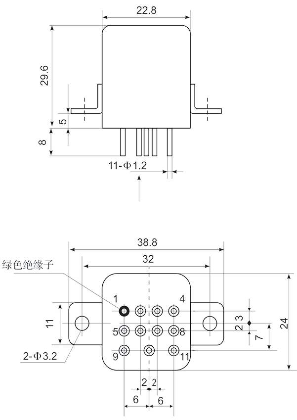
Mechanical drawings |
|
 |
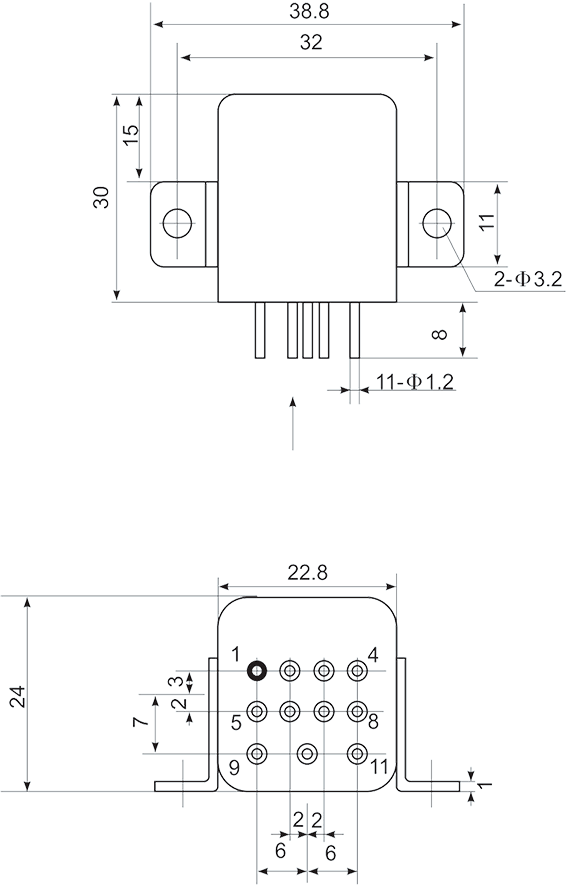 |
| Installation method: C (Installation method 2) | Installation method: B (Installation method: 3) |
| Note: Vibration sensitive direction: Vertical | |
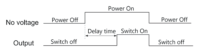
Timing Diagram |
|
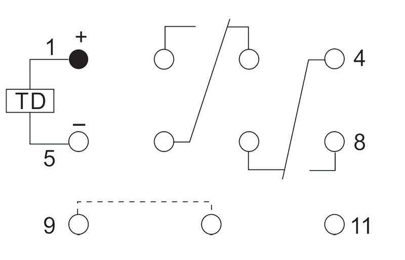
Note When using the product, short-circuit the 9,10 lead rods. If the delay is greater than 70 seconds, the external resistor can be used for adjustment. |
|
Circuit drawing |
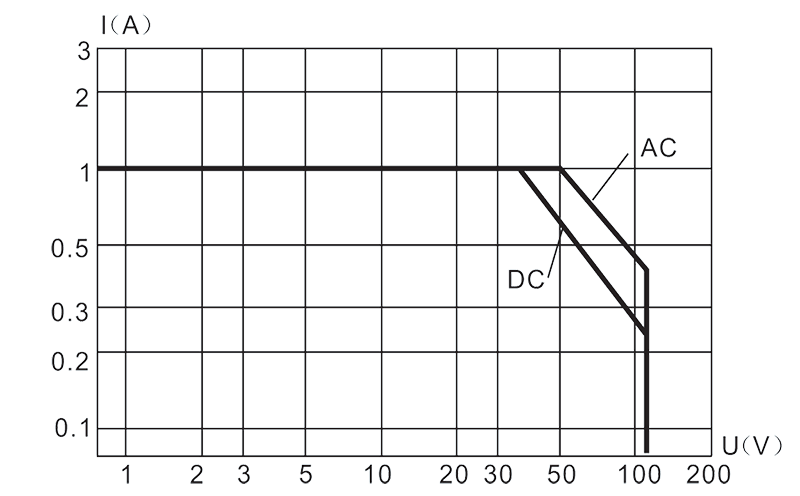
Load characteristic graph |
 |
 |