1JS51-1 Solid Time Delay Relays
Environmental Characteristics
|
No. |
Item | Environmental conditions | |
|
1 |
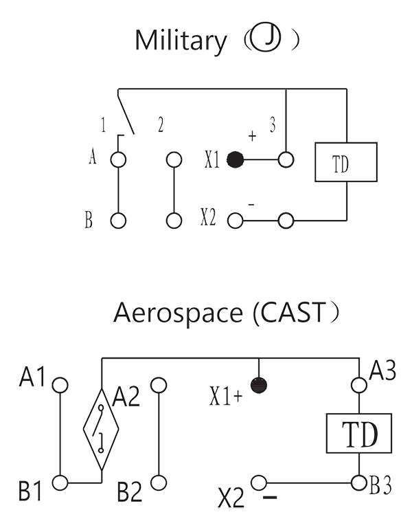
Quality Grade | Military (Ⓙ) | Aerospace (CAST) |
|
2 |
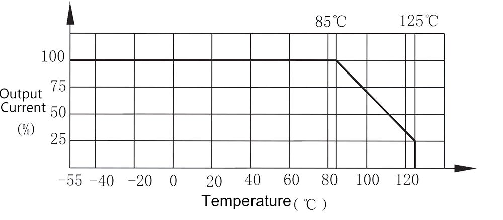
Ambient temperature | -55 °C ~ 125 °C | |
|
3 |
Low air pressure | 0.67 kPa~0.27 kPa | 11.59 kPa |
|
4 |
Sinusoidal vibration | 10 Hz~2000 Hz, 196 m2/s |
10 Hz~3000 Hz, 196 m2/s |
| 5 | Random Vibration | —– |
30 (m/s2)2/Hz |
| 6 | Shock |
735 m/s2, 6ms |
|
| 7 | Constant acceleration |
735 m/s2 |
|
|
Order mark |
RY4.546.060JT: 1JS51-1/28
Note: The accuracy of the delay and the installation method should be stated when ordering. |
CASTPS06/037A-2008: 1JS51-1-28 X t1t2 Z1
Note: The accuracy of the delay and the installation method should be stated when ordering. |
|
Main Specifications
|
Delay type |
Type 5 (user defined) | Output form | 1 group normally open | ||
|
Operating voltage range |
18 VDC~32 VDC | Rated load | 28 VDC, 1A (resistive) | ||
|
Rated operating voltage |
28 VDC | Life time | 1 × 10⁶ cycles or 50h | ||
|
Delay range |
Military | t1: 0.05s~500s
t2: 0.03s~30s |
Dielectric withstand voltage | 250 Vr.m.s., 60s, 1mA | |
|
Aerospace |
t1: 0.05s~500s
t2: 0.03s~500s |
||||
|
Input current |
12mA | Insulation resistance |
1000 MΩ, 500 VDC |
||
| Recycling Time | Military | ≥50 ms | Leak rate | Military |
≤1×10⁻¹ Pa.cm3/s |
| Aerospace | ≥4 s | Aerospace |
≤1×10⁻² Pa.cm3/s |
||
| Power supply instantaneous power off | Military | 50 μs | Weight |
≤12 g |
|
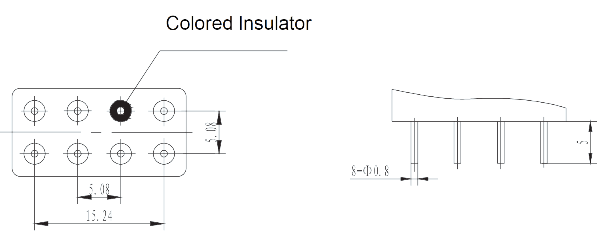
| Aerospace | 200 μs | Dimensions |
20.5mm×10.5mm×15mm |
||
| Delay accuracy | ±2 % | Mounting method |
A(0), C1(1), C(2), B(3) |
||
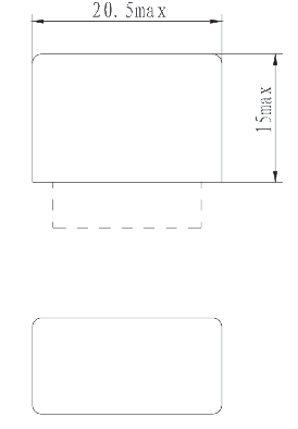
Mechanical drawings
 |
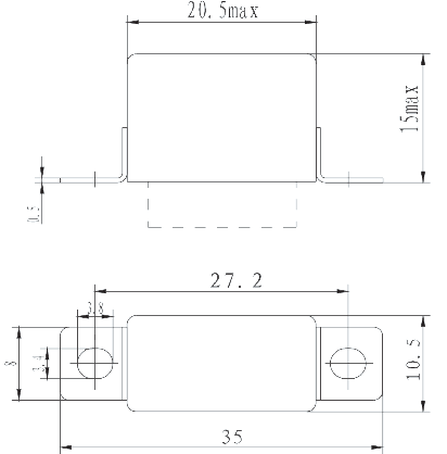 |
| Installation method 0 | Installation method 1 |
 |
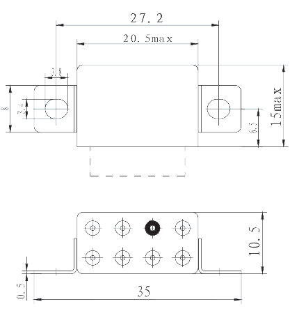 |
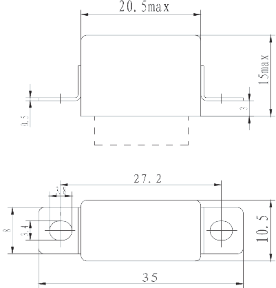
| Installation method 2 | Installation method 3 |
 |
|
| Configuration | |
Timing Diagram |
|
 |
|
Circuit drawing |
Output Current vs. temperature |
 |
 |