2JT10-3 Ultra-small General Electromagnetic Relay
Environmental Characteristics
|
No. |
Parameter | Environmental Specification | |||
|
1 |
Quality Grade | Ⓙ, G | |||
|
II |
IV | V | |||
|
2 |
Temperature Range | (℃) | -55~+125 | -65~125 | |
|
3 |
Relative Humidity | (40±2) ℃, 90%~95% | |||
|
4 |
Low Pressure | (kPa) |
4.39 |
||
| 5 | Sinusoidal Vibration | (Hz) | 10~1000 | 10~2000 |
10~3000 |
| (m/s2) | 147 | 196 |
294 |
||
| 6 | Random vibration | (m/s2)2/Hz | 10 | 20 |
40 |
| 7 | Shock | (m/s2) | 490 | 735 |
980 |
| 8 | Constant Acceleration | (m/s2) | 490 | 735 |
980 |
Main Characteristics
|
Contact Arrangement |
DPDT | Operating Time (ms) | ≤7 | ||
|
Coil Power (W) |
1.3 | Release Time (ms) | ≤4 | ||
|
Leak Rate (Pa.cm3/s) |
≤1×10⁻³ | Load Ratings | Resistive | 10A, 28Vd.c. | |
|
Contact Resistance (Ω) |
Initial | ≤0.05 | 5A, 28Vd.c. | ||
|
After Life |
≤0.1 | Low Level |
10μA~50μA, 10mV~50mV |
||
| Insulation Resistance (MΩ) | Normal | ≥10000 (500Vd.c.) | Life Time (Cycles) | Resistive |
3×10⁴ (10A) |
| High Temp./Humidity | ≥100 (500Vd.c.) |
1×10⁵ (5A) |
|||
| Dielectric Strength (50Hz) | Normal | ≥500 | Low Level |
1×10⁵ |
|
| Low pressure | ≥350 | Weight (g) |
≤13 |
||
Electrical Specification
(Note: Various coil voltage specifications are available upon request.)
|
Coil Voltage (V d.c.) |
25 ℃ | Overall Temperature Range | ||||
|
Rating |
Max. | Coil resistance
(1±10%) Ω |
Operating Voltage V d.c. (max) | Release Voltage V d.c. (min) | Operating Voltage V d.c. (max) | Release Voltage V d.c. (min) |
|
5 |
7 | 25 | 3.3 | 0.3 | 4.6 | 0.1 |
|
6 |
8 | 36 | 4.0 | 0.35 | 5.5 | 0.2 |
|
12 |
15 | 150 | 8.0 | 0.7 | 11.0 |
0.4 |
| 15 | 18 | 220 | 9.0 | 0.9 | 12.0 |
0.5 |
| 18 | 21 | 275 | 12.0 | 1.0 | 16.0 |
0.6 |
| 24 | 28 | 560 | 16.0 | 1.2 | 22.0 |
0.8 |
| 28 | 32 | 600 | 18.0 | 1.5 | 24.0 |
1.0 |
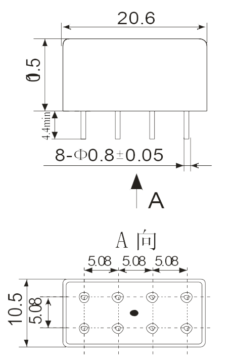
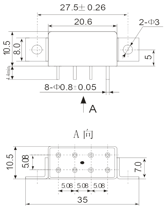
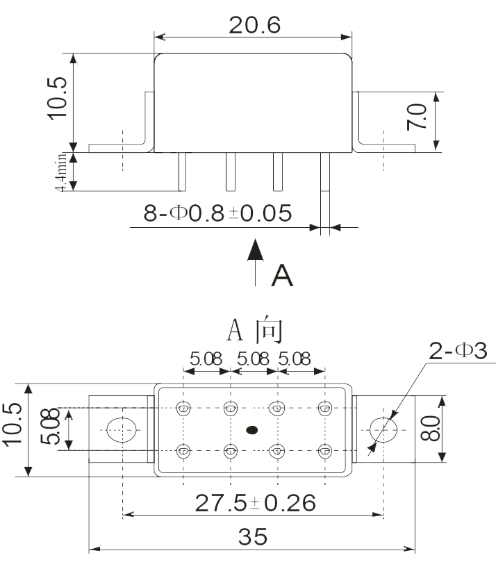
Dimension |
|||
 |
 |
 |
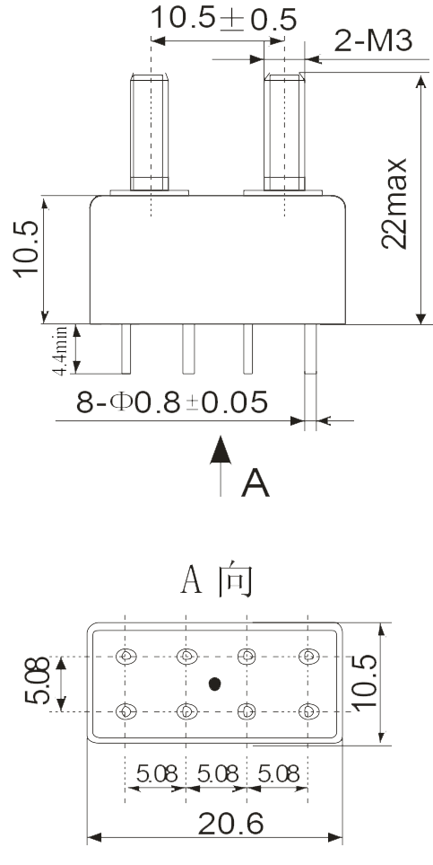 |
| Mounting Style A(0) | Mounting Style B(3) | Mounting Style C(1) | Mounting Style D(4) |
| Note: vibration sensitive direction: horizontal. The different color insulator of the coil lead rod is used for direction identification only. | |||
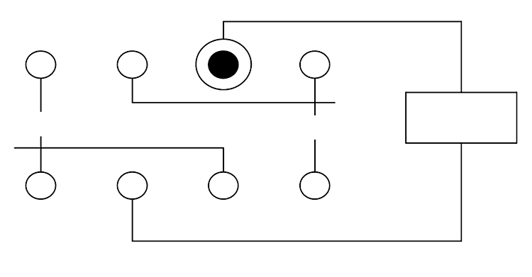
Circuit Diagram |
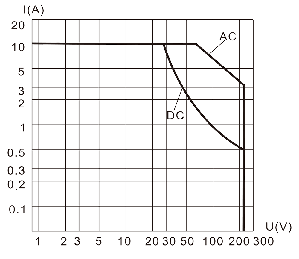
Resistive Load Diagram |
 |
 |
Order mark
J and G grades
- meet the requirements of environmental level:
Example: 2JT10-3/V 28B
| 2JT10-3 | / | V | 28 | B |
| Product number | Environmental rating | Coil voltage | Mounting style |
- Does not meet the requirements of environmental level:
Example:2JT10-3 28B
| 2JT10-3 | – | 28 | B |
| Product number | Coil voltage | Mounting style |
Detailed specification: Q/RYJ01242-2012