2JT5-2 Ultra-small General-Purpose Relay
Environmental Characteristics
|
No. |
Parameter | Environmental Specification | ||||||
|
1 |
Quality Grade | Ⓙ, G | GJB | J/K | Aerospace | |||
|
II |
IV | Ⅴ | ||||||
|
2 |
Temperature Range | (℃) | -55~125 | -65~125 | ||||
|
3 |
Relative Humidity | |||||||
|
4 |
Low Pressure | (kPa) | 0.27~0.013 |
4.39 |
||||
| 5 | Sinusoidal Vibration | (Hz) | 10~2000 | 10~3000 |
10~2000 |
|||
| (m/s2) | 147 | 196 |
294 |
|||||
| 6 | Random vibration | (m/s2)2/Hz | — | — | 40 | 25 |
30 |
|
| 7 | Shock | (m/s2) | 490 | 735 | 980 | 735 |
980 |
|
| 8 | Constant Acceleration | (m/s2) | 490 | 735 | 980 |
735 |
||
Main Characteristics
(The following table list J/K product indicators, other quality levels, please refer to their respective specifications)
|
Contact Arrangement |
DPDT | Operating Time (ms) | ≤6 | ||
|
Coil Power (W) |
≤1.3 | Release Time (ms) | ≤5 | ||
|
Leak Rate (Pa.cm3/s) |
≤1×10⁻³ | Load Ratings | Resistive | 2A, 28V d.c. | |
|
Contact Resistance(Ω) |
Initial | ≤0.05 | 5A, 28Vd.c. (2× 10⁴ cycles) | ||
|
After Life |
≤0.1 | Inductive | 0.5A,28V d.c., 200mH | ||
| Insulation Resistance (MΩ) | Normal | ≥10000 (100Vd.c.) | Light |
0.1A, 28V d.c. |
|
| High Temp./Humidity | ≥100 (100Vd.c.) | Low level |
10~50 µA, 10mV~50mV |
||
| Dielectric Strength (50Hz) | Normal | ≥500 | Life Time (Cycles) |
1×10⁵ |
|
| Low pressure | ≥350 | Overload rating |
Resistive, 10A, 28V d.c., 100 cycles |
||
| Weight (g) | ≤12 | Failure rate |
M level |
||
Electrical Specification
(Note: The values before the brackets in the table are the operating voltages of the J/K products, and the operating voltages of the other quality grades are in the brackets.)
|
Coil Voltage (V d.c.) |
25 ℃ | Overall Temperature Range | ||||
|
Rating |
Max. | Coil resistance
(1±10%) Ω |
Operating Voltage V d.c. (max) | Release Voltage V d.c. (min) | Operating Voltage V d.c. (max) | Release Voltage V d.c. (min) |
|
5 |
7 | 25 | 3.2 | 0.3 | 4.3 | 0.1 |
|
6 |
8 | 36 | 3.9 | 0.4 | 5.2 | 0.2 |
|
12 |
15 | 150 | 7.7 | 0.8 | 10.3 | 0.4 |
| 15 | 18 | 220 | 8.6 | 1.0 | 12.0 |
0.5 |
| 18 | 21 | 275 | 11.6 | 1.2 | 15.4 |
0.6 |
| 24 | 28 | 560 | 15.4 | 1.6 | 21.6 (20.6) |
0.8 |
| 28 | 32 | 600 | 18.0 (16.5) | 2.0 | 23.0 (20.5) |
1.0 |
| 28 | 32 | 980 | 18.0 (17.0) | 2.0 | 24.0 (21.8) |
1.0 |
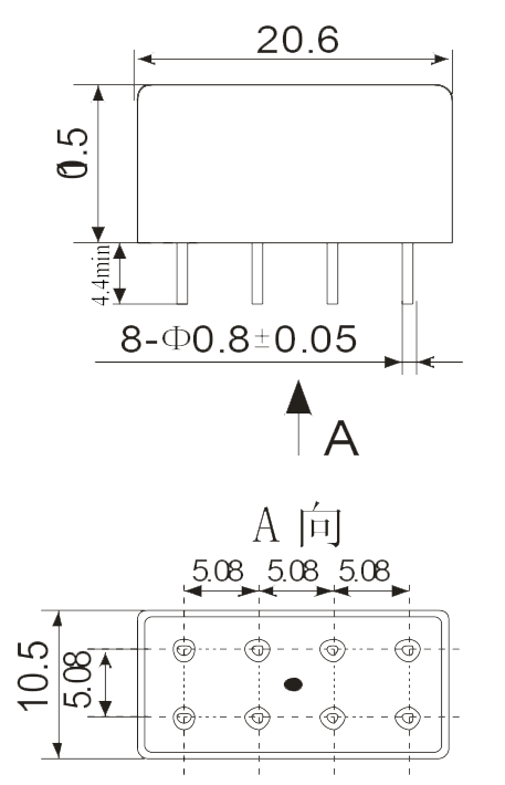
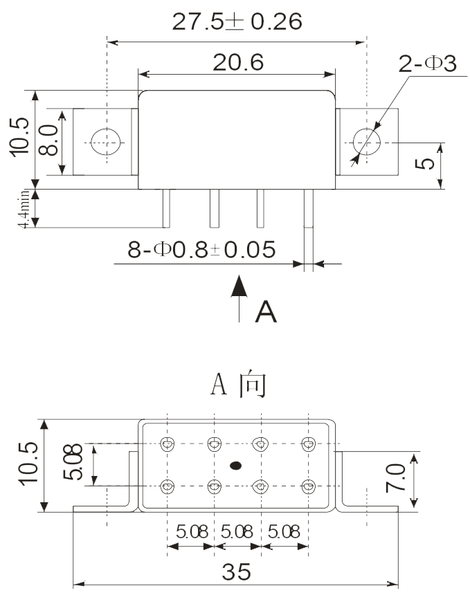
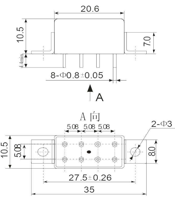
Dimension |
|||
 |
 |
 |
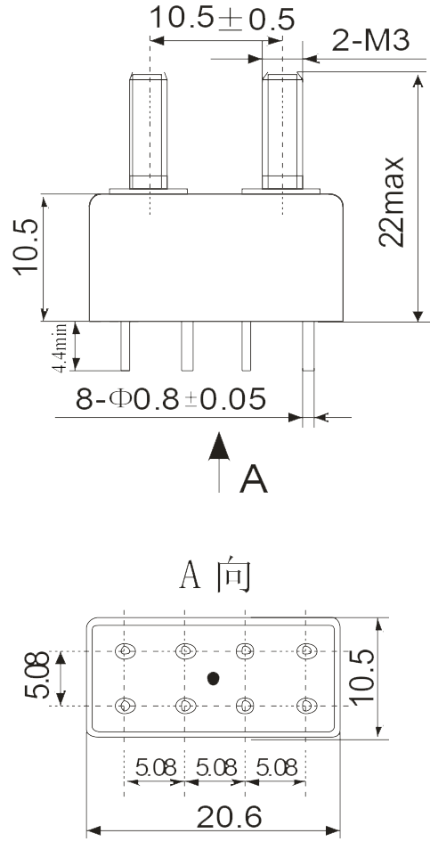 |
| Mounting Style A(0) | Mounting Style B(3) | Mounting Style C(1) | Mounting Style D(4) |
| Note: Vibration sensitive direction: Horizontal | |||
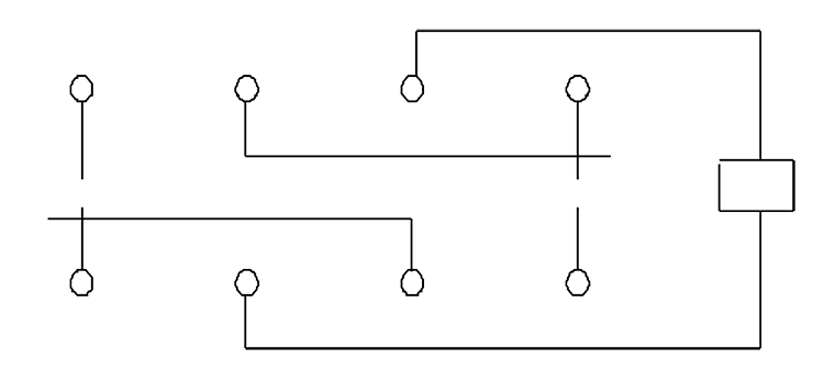
Circuit Diagram |
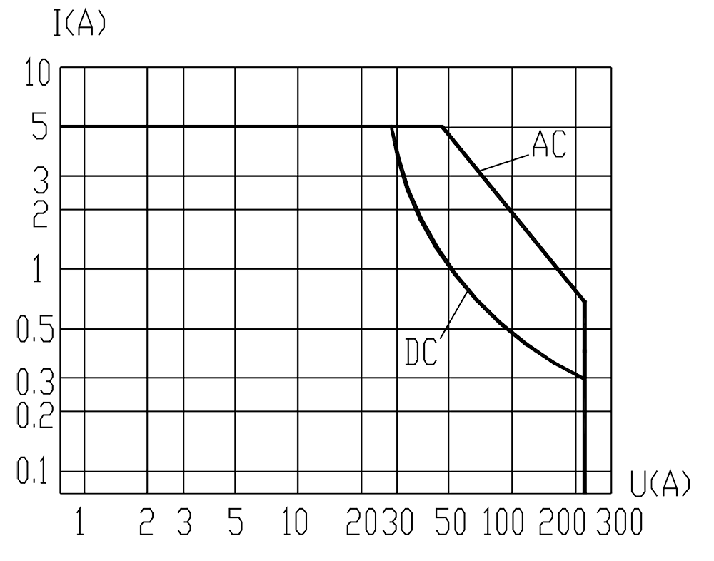
Resistive Load Diagram |
 |
 |
Order Mark
- Military, aerospace grade products:
Example: J65/RY20012-028L/012JT5-2
| J | 65 | / | RY20012 | – | 028 | L | / | 0 | 1 | 2JT5-2 |
| Military sign | General specification number | Detailed specification number | Coil voltage | Failure rate | Mounting style | Terminal form | Product number |
Military standard specification: Q/RY20012-2002
Military Detailed specification: Q/RY-J01137-2007
Note: The aerospace grade products are marked “CB” or “CC” before the order sign.
- J/K grade products:
Example: J65/RY20052-028M/01 2JT5-2
| J | 65 | / | RY20052 | – | 028 | M | / | 0 | 1 | 2JT5-2 |
| Military sign | General specification number | Detailed specification number | Coil voltage | Failure rate | Mounting style | Terminal form | Product number |
Detailed specification: Q/RY20052-2003
- J & G grade products:
Example: 2JT5-2/V 28 B Quality grade (Environmental compliance)
| 2JT5-2 | / | V | 28 | B |
| Mounting style | Coil voltage | Environmental rating | Product number |
Detailed specification: RY4.527.020JT