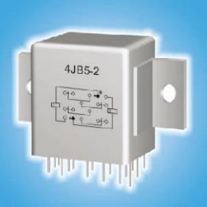
4JB5-3 Magnetic Latching Relays
Environmental Characteristics
| No. | Parameter | Environmental Specification | ||
| 1 | Quality Grade | Ⓙ, G | ||
| II | IV | |||
| 2 | Temp. Range | (°C) | -55~85 | |
| 3 | Relative Humidity | 40℃,90%~95% | ||
| 4 | Low Pressure | (KPa) | 0.67~0.27 | |
| 5 | Sinusoidal Vibration | (Hz) | 10~2000 | |
| (m/s2) | 147 | 196 | ||
| 6 | Random vibration | (m/s2)/Hz | 10 | 20 |
| 7 | Shock | (m/s2) | 490 | 735 |
| 8 | Constant Acceleration | (m/s2) | 490 | 735 |
Main Characteristics
| Contact arrangement | 4 PDT | Operate Time (ms) | ≤20 | ||
| Coil Power (W) | 1.3 | Release Time (ms) | —— | ||
| Leak Rate (Pa.cm3/s) | ≤1×10⁻² | Load
Ratings |
Resistance | 28 Vd.c., 5A | |
|
Contact Resistance (Ω) |
Initial | ≤0.05 | |||
| After life | ≤0.1 | Low Level |
10μA~50μA, 10mV~50mV |
||
|
Insulation Resistance (MΩ) |
Normal | ≥500(500Vd.c.) | |||
| High Temp./ Humidity | ≥10(500Vd.c.) | Life Ratings | 5×10⁴ Cycles | ||
| Dielectric Strength (50Hz) | Normal | 500 Vr.m.s. | |||
| Low Pressure | 250 Vr.m.s. | ||||
| Weight (g) | ≤32 | Reliability Grade | —— | ||
Electrical Specification
| Specification No. | Coil Voltage Vd.c. | 25 ℃ | Overall temperature range | |||
| Normal | Coil Resistance (1±10%) Ω | Pick-up Voltage
Max./ Vd.c |
Drop-out Voltage
Min./ Vd.c. |
Pick-up voltage Max.
/ Vd.c |
Drop-out Voltage
Min./ Vd.c. |
|
| 024 | 24 | 600 | 16 | —— | 20 | —— |
| 028 | 28 | 600 | 18 | —— | 24 | —— |
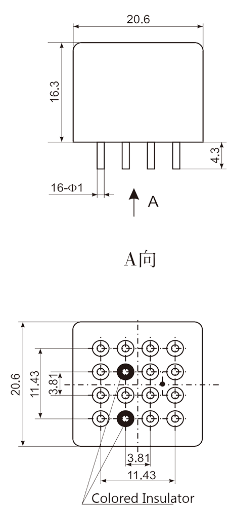
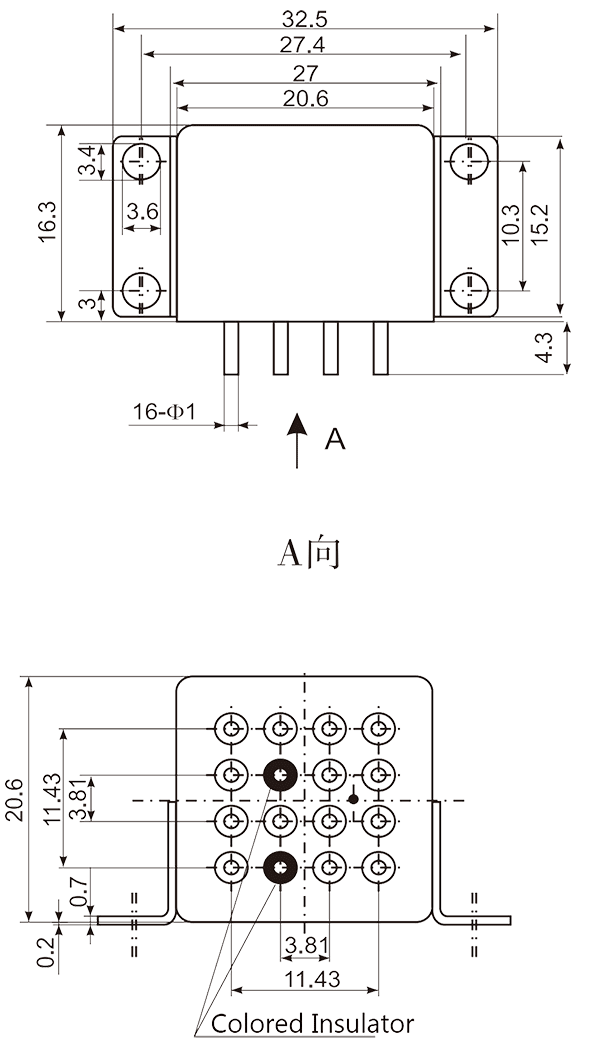
Dimensions |
||
 |
 |
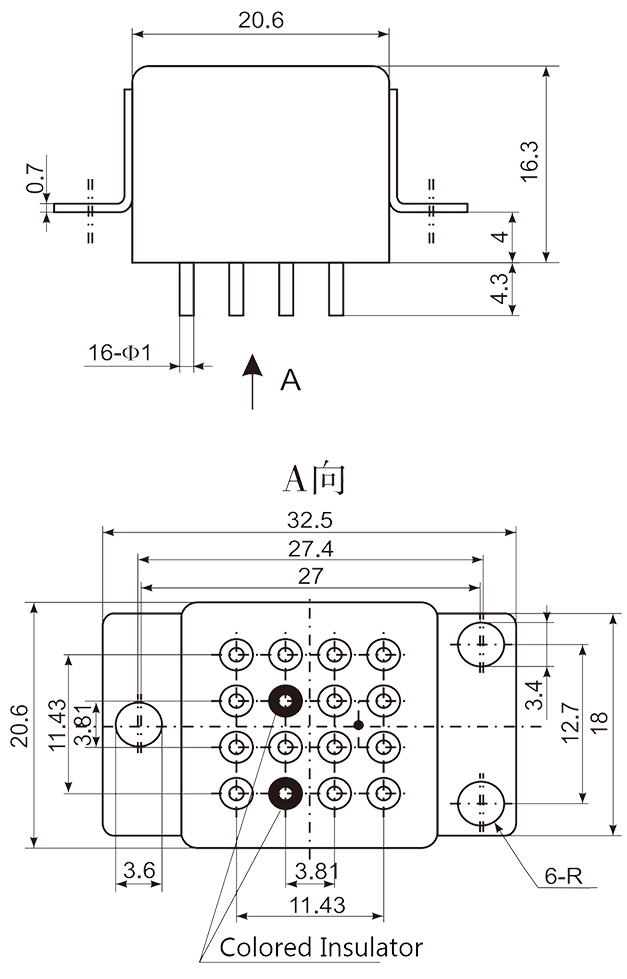 |
| Mounting Style: A (0) | Mounting Style: B (3) | Mounting Style: C (2) |
| Note: Vibration sensitive direction: Vertical | ||
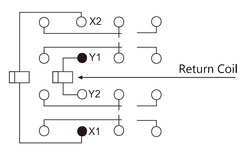
Circuit Diagram |
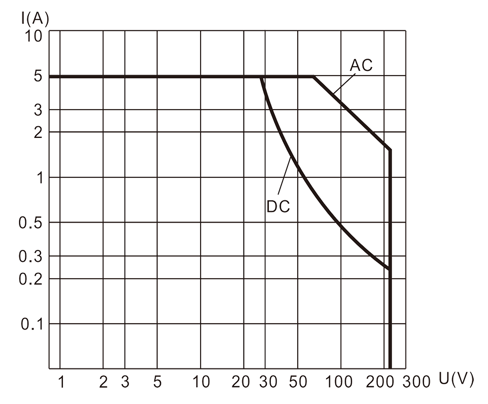
Resistive Load Diagram |
 |
 |
Order Mark
Example: 4JB5-3 /IV 28 C
| 4JB5-3 | / | IV | 28 | C |
| Product Number | Environmental rating | Coil voltage | Mounting style |
Detailed specification: Q/RYJ0160-2000