JF10 series Electrical Connector
Environmental Specifications
|
Operating temperature |
-40 to +85°C | Sinusoidal Vibration | 10 Hz ~ 2000 Hz, 147 m/s2 |
|
Relative humidity |
95% at 40°C | Shock |
735 m/s2 |
| Constant acceleration | 980 m/s2 | Mechanical life |
300 cycles |
Electrical specifications
- Contact resistance and rated current
|
Contact specifications (mm) |
Contact resistance (mΩ) | Rated Current (A) | No. of Contacts | ||
|
JF10-12 |
JF10-48 | JF10-12 |
JF10-48 |
||
|
Φ0.77 |
– | ≤ 8 | 3 | – | 44 |
| Φ1.0 | ≤ 5 | – | 5 | 12 |
– |
| Φ1.5 | – | ≤ 3 | 5 | – |
4 |
Note: The rated current drop rate of multi-core simultaneous operation meets the requirements of the following table:
|
Number of working cores |
1~10 | 11~20 | 21~30 | 31~50 | 51~80 | ≥81 |
| Drop rate % | 0 | 10 | 20 | 30 | 40 |
50 |
Electrical continuity between enclosures ≤5Mω
- Rated voltage, withstand voltage and insulation resistance
|
Working Environment |
Withstand Voltage (Vrms) | Insulation Resistance (MΩ) |
|
Normal Temperature and pressure |
1000 | ≥ 1000 |
|
High humidity |
500 |
≥20 M Ω (JF10-12) ≥10 M Ω (JF10-48) |
| High temperature | — |
≥ 500 |
| Low air pressure: 4.39kpa | 20 |
— |
Mechanical specifications
- Contact: The surface of the copper alloy material is gold plated;
- Mechanical separation force: 15N~70N(JF10-12)
-
-
-
-
- 15N~50N(JF10-48)
-
-
-
-
|
Model |
Head housing | Head cable cover | Housing | Cable cover |
|
JF10-12 |
Aluminum alloy (electroless nickel plating) | Aluminum alloy (electroless nickel plating) | Aluminum alloy (electroless nickel plating) |
– |
| JF10-48 | Composite material (electroless nickel plating and army green Amino-drying enamel spray) | Composite materials (electroless nickel plating and army green Amino-drying enamel spray),
aluminum alloy (electroplated nickel) |
– |
Aluminum alloy (anodized and army green Amino-drying enamel spray) |
Order mark
|
Quality grade |
No mark- Military grade | JF | 10 | – | 48 | TJ | A |
|
Basic serial number |
Rectangular connector | JF | |||||
| Design No. | 10 – Design Sequence Number | 10 | |||||
|
– |
– |
|
|||||
| Contact number |
12, 48 |
48 | |||||
| Connector type | T-plug, J —pin, Z-receptacle, K-socket | TJ |
|
||||
| Improved | TJ (L) – housing and cable cover of the plug, army green Amino-drying enamel spray
TJB— plug and the cable cover material is aluminum alloy ZKA – Vertical outlet receptacle ZKB – Vertical outlet and fixed height receptacle ZKC – Receptacle increased cable cover |
A | |||||
| Example:
JF10-48TJ (L): denoted as a JF10 type 48-core rectangular drop plug (housing and cable cover army green Amino-drying enamel spray). |
|||||||
Model specification
|
Quality level |
Plug model | Feature description | Mating receptacle | Feature description |
|
General level |
JF10-12TJ |
12-pin plug | JF10-12ZK | 12-pin receptacle |
|
JF10-48TJ |
48-pin plug | JF10-48ZK
JF10-48ZKA JF10-48ZKB JF10-48ZKC |
48-pin receptacle Vertical outlet Vertical outlet and fixed height receptacle Self-contained cable cover receptacle |
|
|
JF10-48TJ(L) |
48-pin Plug (housing and cable covers, army green Amino-drying enamel spray) |
|||
| JF10-48TJB |
48-pin plug (the cable cover material is aluminum alloy) |
Receptacle tail attachment (cable cover assembly)
|
Quality level |
Cable cover assembly model | Feature description |
| General level | JF12-48-24 |
Horizontal outlet cable cover (for use with JF10-48ZK receptacle) |
Note: Normally, the receptacle is not equipped with a cable cover. Please choose the one according to your needs.
Contact arrangement
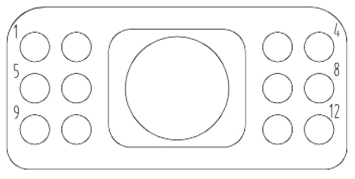 |
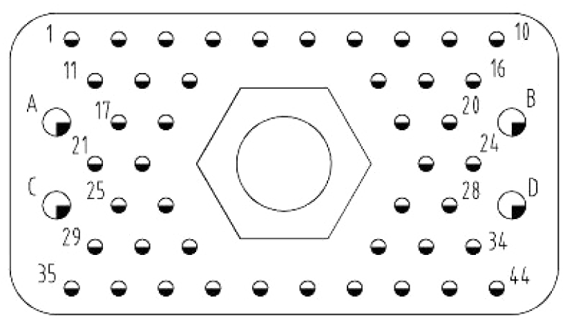 |
| 12 contacts | 48 contacts |
| Contact type | Symbol | Contact specifications | Number of contacts | Contact cup | |||
| 12 contacts | 48 contacts | Inner diameter (mm) | Cross-sectional area (mm2) | Solderable area (mm2) | |||
| Common contact | Φ0.77mm | —— | 44 | Φ1.0 | 0.79 | 0.56 | |
 |
Φ1.0mm | 12 | —— | Φ1.4 | 1.54 | 1.08 | |
 |
Φ1.5mm | —— | 4 | Φ1.8 | 2.54 | 1.78 | |
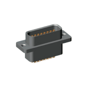
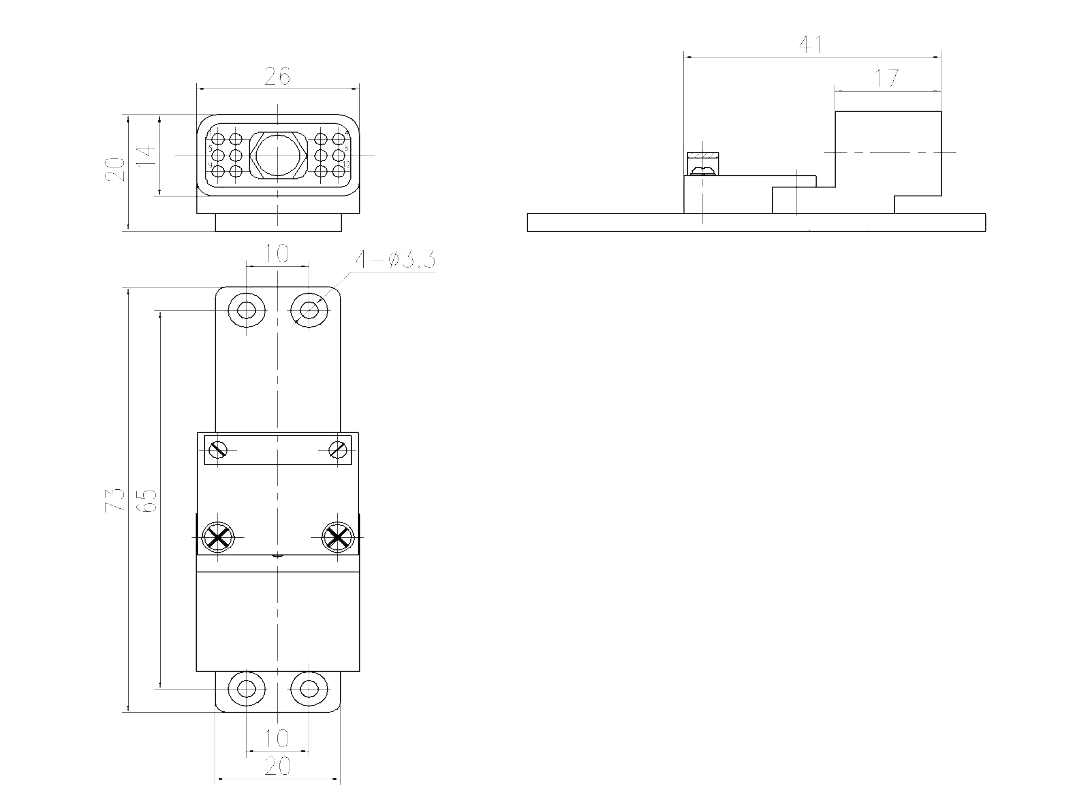
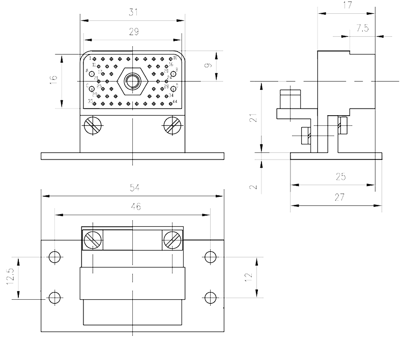
Drawings
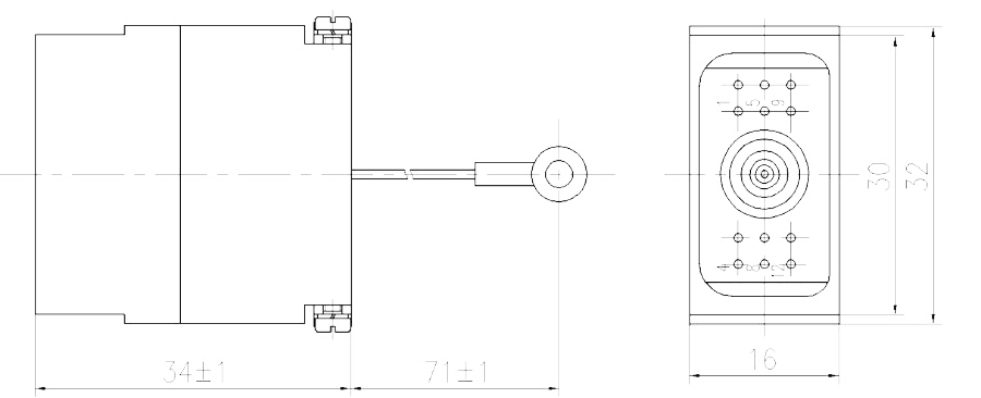 |
 |
| JF10-12TJ Plug | JF10-12ZK Socket |
 |
 |
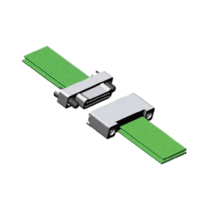
| JF10-48TJ plug, JF10-48TJ (L) plug | JF10-48TJB plug |
 |
 |
| JF10-48ZK Socket | JF10-48ZKA Socket |
 |
 |
| JF10-48ZKB Socket | JF10-48ZKC Socket |
 |
|
| JF10-48-24 Receptacle cable cover | |
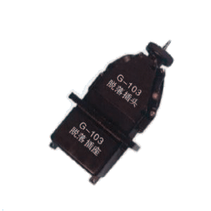
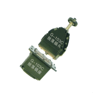
Method of operation
- JF10-12/48 rectangular drop-out electrical connector consists of two parts, a plug and a receptacle. The center of the plug is equipped with a connection mechanism. When the plug and receptacle are directly inserted into position, the steel ball in the connecting mechanism protrudes and snaps into the locking sleeve in the receptacle, so that the head seat is inserted into position.
- When the headstock needs to be separated, a certain axial force is applied to the pull rod or the pull ring, and the steel ball on the connecting mechanism is re-trapped inside the connecting mechanism, thereby unlocking the headstock.