Features
- Wide application. GPS/BD2 dual-mode satellite navigation system with high tracking sensitivity, except for those suitable for open area. It can also be used in complex environments such as streets and jungles.
- Multiple combination modes. Vertical gyro, zero speed correction, inertial /GPS/BD2 multiple combination and multiple mode automatic switch, realizing high reliability parameter output, with the function of external auxiliary equipment combination.
- Adaptable. Silicon micro MEMS devices, with strong anti-shock resistance, and working in full range of -40 °C ~ + 60 °C.
- Excellent performance indicators. The combined navigation horizontal attitude is 0.2° (rms), the position accuracy is better than 15m (rms), the speed accuracy is better than 0.15m/s (rms), the volume is 45mm×45mm×30mm, and the weight is not more than 100g.
- User friendly. Support RS-422, RS-232 multi-channel serial port, adjustable output bandwidth, adjustable output protocol, online uploader/parameter, 9V ~ 40V wide voltage power supply.
Application
- Vehicle navigation system
- Antenna stabilization platform
- Attitude reference system
- Guidance control system
- Measurement of vehicle attitude
- Pipeline inspection system
- Orientation system
- Drilling system
- Mobile mapping system
Performance specifications
Table 1: Main performance indexes of the system
| Gyro | |
| Range | ±400 °/s |
| Zero bias | 30 °/h |
| Zero offset stability | 30 °/h |
| Zero bias repeatability | 100 °/h |
| Scale factor nonlinearity | 1000 ppm |
| bandwidth | 50 Hz ~ 200 Hz |
| Speedometer | |
| Range | ±10 g |
| Zero bias | 1 mg |
| Zero offset stability | 1 mg |
| Zero bias repeatability | 1 mg |
| Scale factor nonlinearity | 1000 ppm |
| Receiver | |
| Frequency Range | BD2 B1/ GPS L1 |
| Gain | 60 s |
| Axial ratio | 10 s |
| Position accuracy | 15 m (rms) |
| Speed accuracy | 0.15 m/s(rms) |
| Antenna | |
| Frequency Range | 1568 ± 10 MHz |
| Gain | >3 (dBi) |
| Axial ratio | <7 (dB) |
| Standing wave | <2 |
| Polarization mode | Right-handed polarization |
| Transmission impedance | 50 Ω |
| Antenna cover material | ABS |
| Installation method | Magnetic |
| Interface form | SMA |
| Antenna ruler (mm) | 50 mm ×51 mm ×15.6 mm |
| Working temperature (°C) | -40 °C ~ 85 °C |
| cable length | RG174-3m(Optional) |
| Weight (g) | 68±2 g |
| waterproof | Fully waterproof |
| Electrical/mechanical interface | |
| power supply | 9 V~40 V |
| Rate | <2.5 W |
| Start time | 3 s |
| Communication Interface | 1 路 RS-422θ1 路 RS-232 |
| Update rate | 100 Hz~1000 Hz |
| Dimensions (without mounting ears) | 45 mm×45 mm×30 mm |
| Installation size (including mounting ears) | 58 mm×45 mm×30 mm |
| Weight | <100 g |
| Operating Condition | |
| Operating temperature | -40 °C~60 °C |
| Vibration | 6.06 g(rms) |
| Shock | 9 g/11ms; 1000 g/1ms |
| Composite navigation performance | |
| Position accuracy | 15 m (rms) |
| Speed accuracy | 0.15 m/s (rms) |
| Horizontal posture | 0.2° (rms) |
| Heading accuracy | Typical vehicle environment 1° (rms, depending on carrier dynamics) |
External communication
- Low frequency connector: Y34M-11SH
- Rf connector: SMA
Table 2: system external point definition
| No. | Definition | Remarks |
| 1 | VCC | 9V ~ 40V |
| 2 | GND | GND |
| 3 | RS232RXD | INS receive |
| 4 | RS232TXD | INS send |
| 5 | RS232GND | GND |
| 6 | RS422-1-R+ | INS receive + |
| 7 | RS422-1-R- | INS receive – |
| 8 | RS422-1-T- | INS send – |
| 9 | RS422-1-T+ | INS send + |
| 10 | Receiver 232 TXD | Receiver send |
| 11 | Receiver 232 GND | GND |
The system’s external RS-422/RS-232 communication protocol can be customized according to user requirements. The default RS-422 communication rate of the system is 921600bps, the data period is 1ms, the default baud rate of RS-232 communication is 115200bps, and the data period is 10ms.
Table 3: System Communication Protocol
| Section No. | Format | Content | Unit | Resolution | Description |
| 1 | Unsigned Char | 0x55 | ˉ | ˉ | Frame header |
| 2 | Unsigned Char | 0xAA | ˉ | ˉ | Frame header |
| 3 | Unsigned Char | 0x44 | ˉ | ˉ | Data length |
| 4~7 | Unsigned Int | ˉ | ms | 1 | Navigation time |
| 8~11 | ˉ | ˉ | ˉ | ˉ | System reserved word |
| 12~15 | ˉ | ˉ | °/s | IEEE 32 bit | X angular rate |
| 16~19 | ˉ | ˉ | °/s | IEEE 32 bit | Y angular rate |
| 20~23 | ˉ | ˉ | °/s | IEEE 32 bit | Z angular rate |
| 24~27 | ˉ | ˉ | m/s2 | IEEE 32 bit | X acceleration |
| 28~31 | ˉ | ˉ | m/s2 | IEEE 32 bit | Y acceleration |
| 32~35 | ˉ | ˉ | m/s2 | IEEE 32 bit | Z acceleration |
| 36~39 | ˉ | ˉ | m/s | IEEE 32 bit | North speed |
| 40~43 | ˉ | ˉ | m/s | IEEE 32 bit | Speed |
| 44~47 | ˉ | ˉ | m/s | IEEE 32 bit | East speed |
| 48~51 | ˉ | ˉ | m | IEEE 32 bit | height |
| 52~55 | Int | ˉ | ° | 1e-7 | Twist |
| 56~59 | Int | ˉ | ° | 1e-7 | latitude |
| 60~63 | ˉ | ˉ | ° | IEEE 32 bit | scroll |
| 64~67 | ˉ | ˉ | ° | IEEE 32 bit | course |
| 68~71 | ˉ | ˉ | ° | IEEE 32 bit | Pitch |
| 72 | Unsigned Char | ˉ | ˉ | ˉ | Checksum |
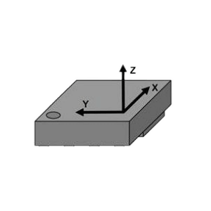
| Notes: 1. The total frame length is N, and the data length in the frame is N-4;2. The roll angle range (-180, 180) is positive for right turn; the range of heading angle (-180, 180) is positive for north to west, and the head for pitch angle (-90 90) is positive.3. XYZ is the carrier coordinate system, the X axis points to the longitudinal axis of the carrier, and XYZ points to the front, the right, and the right direction of the carrier.4. The checksum takes the 3rd to 71st bytes of the accumulated sum and takes the lower eight bits. |
|||||