Y11 Series Connector
Environmental Specifications
- Operating temperature: -55 to +125°C
- Relative humidity: 90-95% at 40±2°C
- Operating pressure: 101.33 kPa~4.39 kPa
- Rain proof: Rainfall capacity 5 mm/min
- Salt spray: 48h (P, X, H), 96h (S)
- Hermetic Sealing: Glue sealed receptacle 0.2MPa; Glass sealing receptacle no more than 1×10⁻⁵ Pa·L/s
Electrical Specifications
- Characteristics of contact
|
Diameter of pin (mm) |
Ø1 | Ø1.5 | ||
|
Operation current (A) |
5 | 10 | ||
| Materials | Copper alloy |
Ferrous alloy |
Copper alloy |
Ferrous alloy |
| Contact Resistance (mΩ) | ≤5 | ≤15 | ≤3 |
≤10 |
- Insulation Resistance
|
Standard atmospheric condition |
Wet | Rainy | High-temperature |
| ≥3000 MΩ | ≥20 MΩ | ≥20 MΩ |
≥500 MΩ |
- Voltage resistance
|
Standard condition |
Low pressure condition | Hot and Humid conditions |
| AC 1500 Vrms | AC 200 Vrms |
AC 500 Vrms |
Electrical continuity between the shells: not more than 200 mΩ
Electromagnetic interference (P class): at 800 MHz, the lowest attenuation is 45 dB
Mechanical Specifications
- Housing: aluminum alloy (X, P), iron-nickel alloy (H), copper alloy (S), stainless steel (D)
- Plating: Class X – black anodized, non-conductive shell; P class – Electroless nickel plating, conductive shell;
- Class H – Nickel plated, conductive housing; Class S – Nickel plated, conductive housing; Class D – Anodized
- Insulator: thermoplastic engineering plastics
- Rubber pad: silicone rubber material
- Contact: copper alloy material, iron-nickel alloy material (only H class)
- Sinusoidal vibration: 10Hz ~ 50Hz, double amplitude 2mm 50Hz ~ 2000Hz, 196m/s2
- Random vibration: The power spectral density is 4g2/Hz, and the root mean square value is 239.1m/s2.
- Shock: 980 m/s2
- Mechanical life: 500 times (P class 250 times)
Ordering Format
| Y11 | X | II | – | 20 | 41 | Z | J | 10 | – | 2 | |
| Y11 series | Y11 | ||||||||||
Category:
|
X | ||||||||||
Insulation mounting plate position change number:
|
II | ||||||||||
Housing number:
|
20 | ||||||||||
Contact arrangements:
|
41 | ||||||||||
Shell type:
|
Z | ||||||||||
Contact type:
|
J | ||||||||||
Socket installation:
|
10 | ||||||||||
Cable cover form:
|
2 |
Note: socket installation mode sign is only available for sockets, the plug does not have the sign.
Ordering Guide:
- The user can order according to the required functions, and the manufacturer assembles and supplies according to the functions required by the user to achieve reasonable and economical use.
- Special orders must refer to the above special component structure, order by component code. The component code is Y11-××OO-80, Y11-××OO-81, Y11-××OO-83, Y11-××OO-84, Y11-××OO-85, Y11-××OO-86, Y11-××OO-87, Y11-××OO-88, and Y11-×× OO-89. If there is “××OO” in the middle of the mark number, it means that the shell number can be selected at will. For example, if you want to order for the plug metal dust cover of housing No. 14, write Y11-1400-80 on the order form; if you want to order the metal dust cover of the housing No. 10 receptacle, write Y11-1000-81; To order the housing No.18 empty receptacle, write it on Y11-1800-83;
- The headstock cable cover of Y11S series needs to be ordered separately, the code is Y11-××00-93, and the structure is the clamped wire cable cover.
Dimensions
 |
Shell | A | MD | H | L±2 |
| 08 | Φ20 | M14*1 | Φ6 | 39 | |
| 10 | Φ23 | M18*1 | Φ8 | 39 | |
| 12 | Φ26 | M20*1 | Φ10 | 41 | |
| 14 | Φ30 | M24*1 | Φ12 | 47 | |
| 16 | Φ33 | M27*1 | Φ14 | 47 | |
| 18 | Φ36 | M30*1 | Φ17 | 47 | |
| 20 | Φ39 | M33*1.5 | Φ20 | 49 | |
| 22 | Φ42 | M36*1.5 | Φ24 | 49 | |
| 24 | Φ45 | M39*1.5 | Φ27 | 54 |
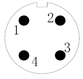
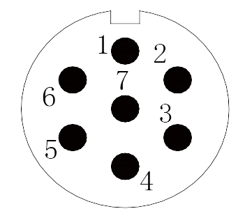
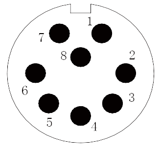
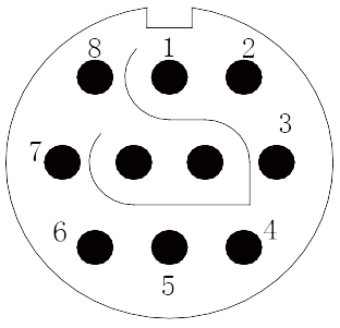
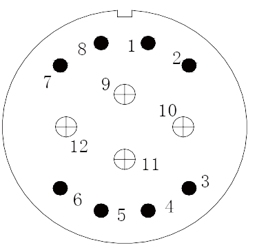
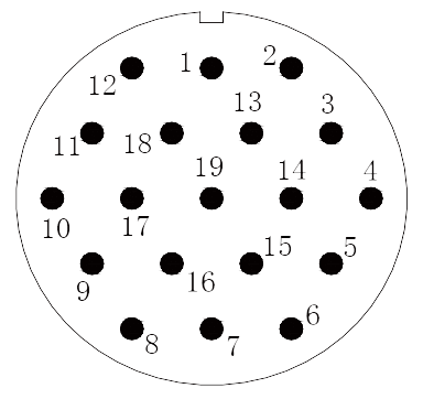
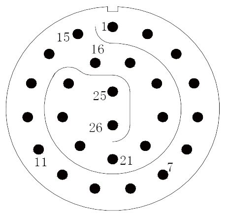
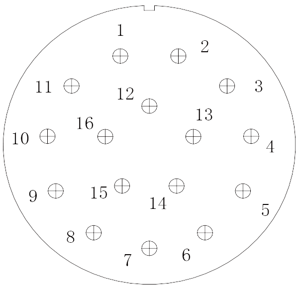
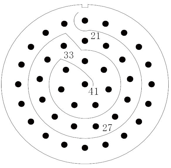
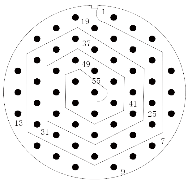
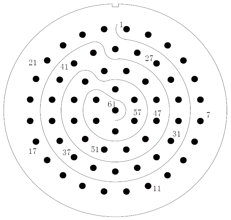
Contact arrangement
 |
||
 |
 |
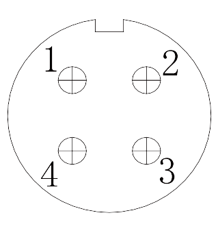 |
| 0804 | 1007 | 1204 |
 |
 |
 |
| 1208 | 1210 | 1412 |
 |
 |
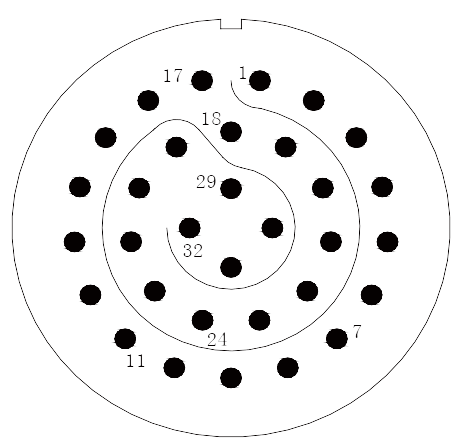 |
| 1419 | 1626 | 1832 |
 |
 |
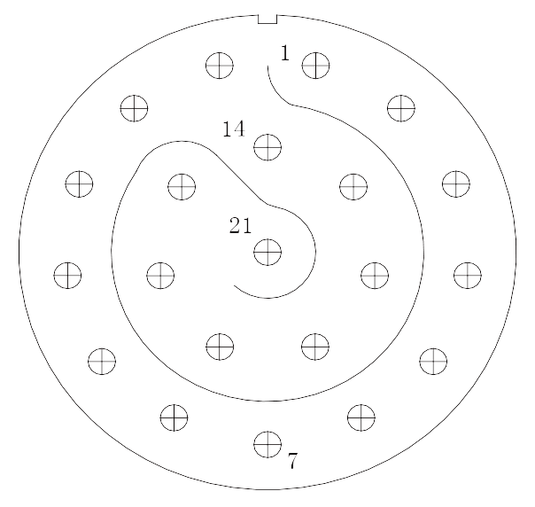 |
| 2016 | 2041 | 2221 |
 |
 |
|
| 2255 | 2461 | |
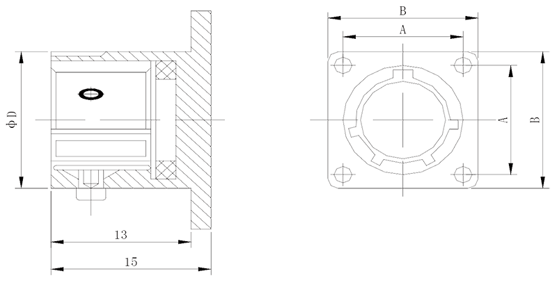
Square flange socket
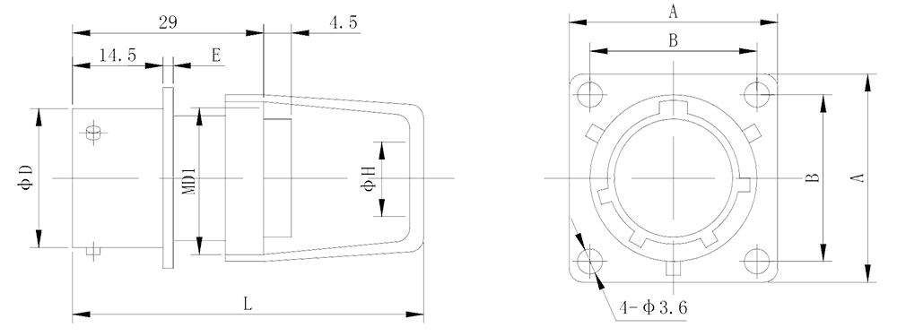 |
Shell | A | B | D | E | MD1 | H | L±2 |
| 08 | 21 | 15±0.15 | 13 | 1.5 | M14*1 | 6 | 39.5 | |
| 10 | 24 | 18±0.15 | 16 | 1.5 | M18*1 | 8 | 39.5 | |
| 12 | 27 | 21±0.15 | 20 | 1.5 | M20*1 | 10 | 41. 5 | |
| 14 | 30 | 23±0.15 | 23 | 1.5 | M24*1 | 12 | 47.5 | |
| 16 | 33 | 25+0.15 | 26 | 1.5 | M27*1 | 14 | 47.5 | |
| 18 | 36 | 27±0.15 | 29 | 1.5 | M30*1 | 17 | 47.5 | |
| 20 | 39 | 29±0.15 | 32 | 2.2 | M33*1.5 | 20 | 49.5 | |
| 22 | 42 | 32±0.15 | 35 | 2.2 | M36*1.5 | 24 | 49.5 | |
| 24 | 45 | 35+0.15 | 38 | 2.2 | M39*1.5 | 27 | 54.5 |
Wall mount square flange receptacle
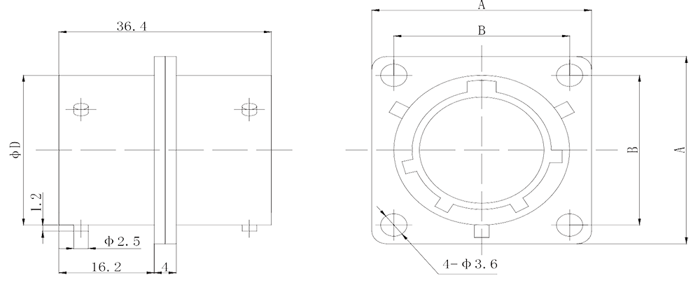 |
Shell | A | B | D |
| 08 | 21 | 15±0.15 | Φ13 | |
| 10 | 24 | 18±0.15 | Φ16 | |
| 12 | 27 | 21±0.15 | Φ20 | |
| 14 | 30 | 23±0.15 | Φ23 | |
| 16 | 33 | 25±0.15 | Φ26 | |
| 18 | 36 | 27±0.15 | Φ29 | |
| 20 | 39 | 29±0.15 | Φ32 | |
| 22 | 42 | 32±0.15 | Φ35 | |
| 24 | 45 | 35±0.15 | Φ38 |
Square flange glass sintered receptacle
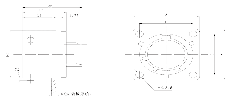 |
Shell | A | B | DI | K |
| 08 | 21 | 15±0.15 | Φ13 | 3.5 | |
| 10 | 24 | 18±0.15 | Φ16 | 3.5 | |
| 12 | 27 | 21±0.15 | Φ20 | 3.5 | |
| 14 | 30 | 23±0.15 | Φ23 | 3.5 | |
| 16 | 33 | 25±0.15 | Φ26 | 3.5 | |
| 18 | 36 | 27±0.15 | Φ29 | 3.5 | |
| 20 | 39 | 29±0.15 | Φ32 | 3.5 | |
| 22 | 42 | 32±0.15 | Φ35 | 3.5 | |
| 24 | 45 | 35±0.15 | Φ38 | 3.5 |
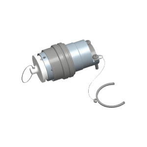
Round flange receptacle (with clamped cable cover assembly)
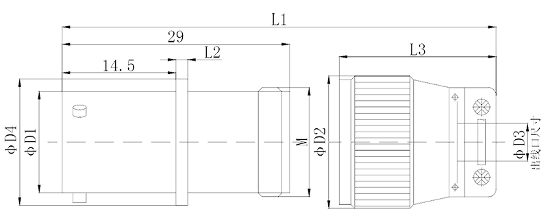 |
Shell | DI | D2 | D3 | D4 | M | L3 | L2 | Ll±2 |
| 08 | 13 | 17 | 6 | 16.2 | M14*1 | 20 | 1.5 | 39.5 | |
| 10 | 16 | 20 | 8 | 19 | M18*1 | 20 | 1.5 | 39.5 | |
| 12 | 20 | 22.5 | 10 | 23 | M20*1 | 22 | 1.5 | 41. 5 | |
| 14 | 23 | 26.5 | 12 | 26 | M24*1 | 28 | 1.5 | 47.5 | |
| 16 | 26 | 29.5 | 14 | 29 | M27*1 | 28 | 1.5 | 47.5 | |
| 18 | 29 | 32.5 | 17 | 32 | M30*1 | 28 | 1.5 | 47.5 | |
| 20 | 32 | 35.5 | 20 | 35 | M33*1.5 | 30 | 2.2 | 49.5 | |
| 22 | 35 | 38.5 | 24 | 38 | M36*1.5 | 30 | 2.2 | 49.5 | |
| 24 | 38 | 41.5 | 27 | 41 | M39*1.5 | 35 | 2.2 | 54.5 |
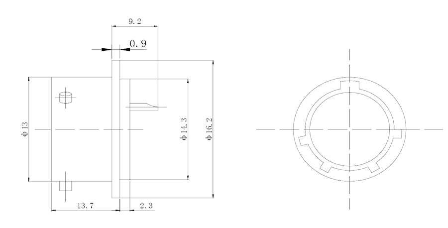
Nut mounting Receptacle
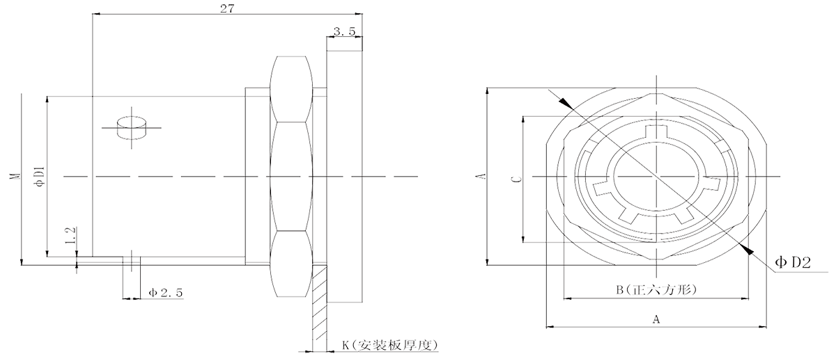 |
Shell | DI | D2 | A | B | C | M | K |
| 08 | 13 | 27 | 24 | 22 | 15 | M16X1 | 1.6-8 | |
| 10 | 16 | 31 | 27 | 24 | 19 | M20X1 | 1.6-8 | |
| 12 | 20 | 35 | 32 | 27 | 23 | M24X1 | 1.6-8 | |
| 14 | 23 | 38 | 36 | 30 | 26 | M27X1 | 1.6-8 | |
| 16 | 26 | 42 | 38 | 32 | 29 | M30X1 | 1.6-8 | |
| 18 | 29 | 45 | 41 | 36 | 32 | M33X1.5 | 1.6-8 | |
| 20 | 32 | 49 | 46 | 41 | 35 | M36X1.5 | 1.6-8 | |
| 22 | 35 | 53 | 50 | 43 | 38 | M39X1.5 | 1.6-8 | |
| 24 | 38 | 56 | 53 | 46 | 41 | M42X1.5 | 1.6-8 |
Nut mounting glass sintered receptacle
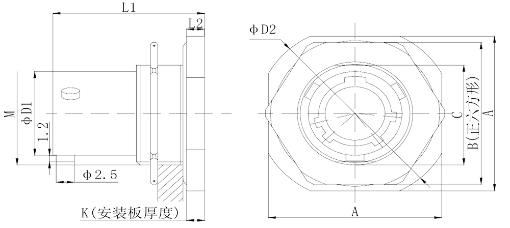 |
Shell | DI | D2 | A | B | C | M | L2 | LI | K |
| 08 | 13 | 27 | 24 | 22 | 15 | M16*1 | 2.5 | 21 | 1.6-3.2 | |
| 10 | 16 | 31 | 27 | 24 | 19 | M20*1 | 2.5 | 21 | 1.6-3.2 | |
| 12 | 20 | 35 | 32 | 27 | 23 | M24*1 | 2.5 | 21 | 1.6-3.2 | |
| 14 | 23 | 38 | 36 | 30 | 26 | M27*1 | 2.5 | 21 | 1.6-3.2 | |
| 16 | 26 | 42 | 38 | 32 | 29 | M30*1 | 2.5 | 21 | 1.6-3.2 | |
| 18 | 29 | 45 | 41 | 36 | 32 | M33*1.5 | 2.5 | 21 | 1.6-3.2 | |
| 20 | 32 | 49 | 46 | 41 | 35 | M36*1.5 | 3 | 25.5 | 1.6-6.4 | |
| 22 | 35 | 53 | 50 | 43 | 38 | M39*1.5 | 3 | 25.5 | 1.6-6.4 | |
| 24 | 38 | 56 | 53 | 46 | 41 | M42*1.5 | 3 | 25.5 | 1.6-6.4 |
Y11H-0804ZJ11 Round flange glass sintered receptacle
Accessory outline drawing
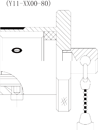 |
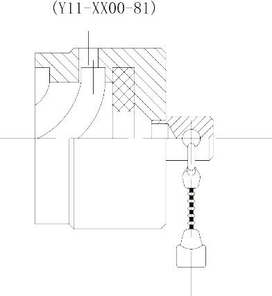 |
| Plug metal dust cover | Receptacle metal dust cover |
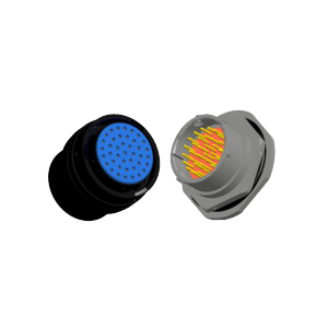
Empty receptacle assembly (Y11 ××OO 83)
 |
Shell | 08 | 10 | 12 | 14 | 16 | 18 | 20 | 22 | 24 |
| D | 13 | 16 | 20 | 23 | 26 | 29 | 32 | 35 | 38 | |
| A | 21 | 24 | 27 | 30 | 33 | 36 | 39 | 42 | 45 | |
| B | 15 | 18 | 21 | 23 | 25 | 27 | 29 | 32 | 35 |
Open long cable cover (Y11 ××OO 85)
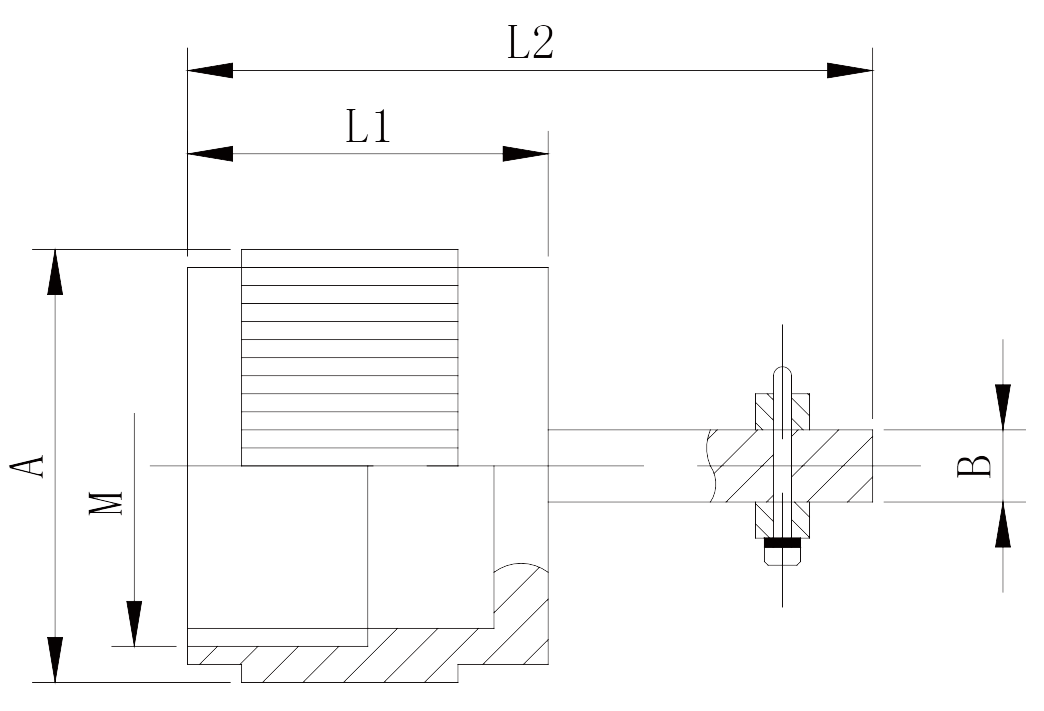 |
Shell | A | L1 | L2 | B | M | Outlet |
| 08 | Φ17 | 15 | 29 | 2. 5 | 14*1 | Φ10 | |
| 10 | Φ20 | 15 | 29 | 2.5 | 18*1 | Φ12 | |
| 12 | Φ24.5 | 15 | 31 | 2. 5 | 20*1 | Φ14 | |
| 14 | Φ26.5 | 15 | 31 | 3 | 24*1 | Φ16 | |
| 16 | Φ29.5 | 20 | 38 | 3 | 27*1 | Φ18 | |
| 18 | Φ32.5 | 20 | 39 | 4 | 30*1 | Φ20 | |
| 20 | Φ35.5 | 20 | 40 | 4.5 | 33*1.5 | Φ20 | |
| 22 | Φ38.5 | 22 | 42 | 5 | 36*1.5 | Φ22 | |
| 24 | Φ41.5 | 22 | 42 | 5 | 39*1.5 | Φ24 |
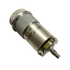
Shielded cable cover (Y11 ××OO 86)
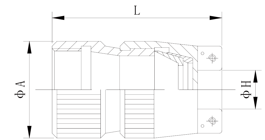 |
Shell | L | A | H | Shell | L | A | H |
| 08 | 35 | 19 | 10 | 18 | 50 | 34 | 20 | |
| 10 | 35 | 21 | 14.5 | 20 | 50 | 37 | 22.5 | |
| 12 | 37 | 25.5 | 14. 5 | 22 | 50 | 38.5 | 22.5 | |
| 14 | 40 | 29 | 16. 5 | 24 | 50 | 41. 5 | 24 | |
| 16 | 40 | 30 | 16. 5 |
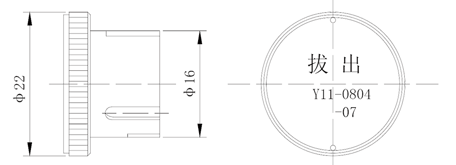
Short circuit cap (Y11-0804-87)
Long cable cover assembly
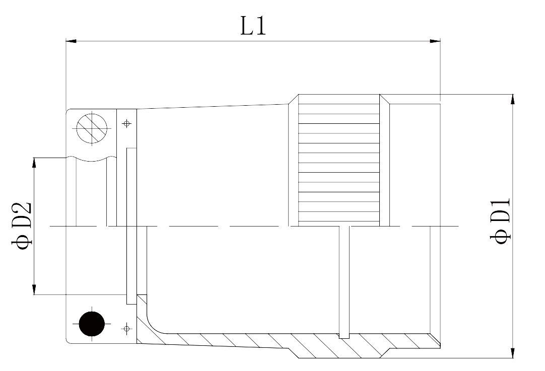 |
Shell | DI | D2 | LI | MC | D | LI | L2 |
| 08 | 17 | 6 | 35 | 14*1 | 17 | 29 | 35 | |
| 10 | 20 | 8 | 35 | 18*1 | 20 | 29 | 35 | |
| 12 | 22.5 | 10 | 37 | 20*1 | 22.5 | 30 | 37 | |
| 14 | 26.5 | 12 | 43 | 24*1 | 26.5 | 34 | 43 | |
| 16 | 29.5 | 14 | 43 | 27*1 | 29.5 | 34 | 43 | |
| 18 | 32.5 | 17 | 43 | 30*1 | 32.5 | 34 | 43 | |
| 20 | 35.5 | 20 | 45 | 33*1.5 | 35.5 | 36 | 45 | |
| 22 | 38.5 | 24 | 45 | 36*1.5 | 38.5 | 36 | 45 | |
| 24 | 41.5 | 27 | 50 | 39*1.5 | 41.5 | 41 | 50 |
Note: Y11-×× 00-88 aluminum alloy black anodized, Y11-×× 00-88c aluminum alloy nickel plating
Heat shrinkable sleeve type 1 cable cover assembly (Y11-××00-84, 45 steel tin plated)
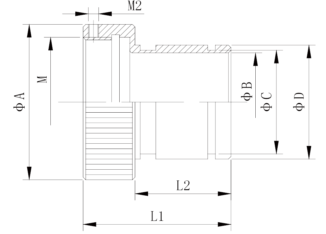 |
Shell | LI | L2 | A | B | C | D | M | M2 |
| 08 | 27 | 15 | 20 | 9 | 11 | 13 | 14*1 | 2.5 | |
| 10 | 27 | 15 | 24 | 10 | 12 | 14 | 18*1 | 2.5 | |
| 12 | 30 | 15 | 26.5 | 13 | 15 | 17 | 20*1 | 2.5 | |
| 14 | 31 | 16 | 30. 5 | 17 | 19 | 21 | 24*1 | 3 | |
| 16 | 31 | 18 | 33 | 18 | 20 | 22 | 27*1 | 3 | |
| 18 | 34 | 22 | 36 | 23 | 25 | 27 | 30*1 | 3 | |
| 20 | 35 | 20 | 39.5 | 24 | 26 | 28 | 33*1.5 | 3 | |
| 22 | 34 | 22 | 42 | 27 | 29 | 31 | 36*1.5 | 3 | |
| 24 | 36 | 24 | 45 | 30 | 32 | 34 | 39*1.5 | 3 |
Heat shrinkable sleeve type 2 cable cover assembly (Y11-××00-89, 45 steel tin plated)
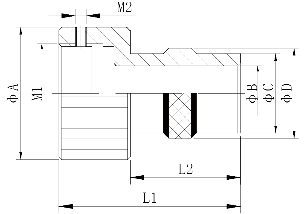 |
Shell | A | B | C | D | Ml | LI | L2 | M2 |
| 08 | 20 | 8.7 | 12.8 | 14.8 | 14*1 | 33 | 20 | 2.5 | |
| 10 | 24 | 10 | 14.4 | 16.4 | 18*1 | 33 | 20 | 2.5 | |
| 12 | 26.5 | 15 | 19.1 | 21.1 | 20*1 | 33 | 20 | 2.5 | |
| 14 | 30.5 | 18.2 | 22.3 | 24.3 | 24*1 | 33 | 20 | 3 | |
| 16 | 33 | 18.2 | 22.3 | 25.3 | 27*1 | 33 | 20 | 3 | |
| 18 | 36 | 24.5 | 28.7 | 30.7 | 30*1 | 33 | 20 | 3 | |
| 20 | 39.8 | 24.5 | 28.7 | 30.7 | 33*1.5 | 33 | 20 | 3 | |
| 22 | 42 | 27.7 | 30.8 | 33.8 | 36*1.5 | 35 | 20 | 3 | |
| 24 | 45 | 30 | 31.8 | 34 | 39*1.5 | 35 | 20 | 3 |