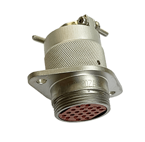
Y16 series Circular Electrical Connector
Environmental Specifications
| Operating temperature | -55 to +125°C | Sinusoidal Vibration | 10 ~ 50 Hz, single amplitude 1.5 mm
(Z type: 2.0 mm) 50 Hz ~ 2000 Hz, 196 m/s2 |
| Working pressure | 101.3kPa ~ 6.67Pa | ||
| Relative humidity | 40± 2℃ @ 92% ~ 98% | Fungus | GJB150.10A, class 2 |
| Mechanical life | 1000 cycles
500 cycles (Y16N) |
Shock | 392 m/s2, 10 ms 980 m/s2, 3 ms |
| Rain fall | 5 mm/min | Hermetic Seal | Ordinary Seal≥ 98 KPa Glass sintering seal ≤1×10⁻⁵ Pa.L/s |
Electrical specifications
- Contact resistance and rated current
| Contact diameter (mm) | 1 | 1.3 | 1.5 | 2.5 | 3 | 3.5 | 5 |
| Rated Current (A) | 5 | 7 | 10 | 25 | 30 | 60 | 75 |
| Contact resistance (mΩ) Φ1.0 | ≤ 5 | ≤ 4 | ≤ 3 | ≤ 1 | ≤ 1 | ≤ 1 | ≤ 1 |
- Rated voltage, withstand voltage and insulation resistance
| Working Environment | Withstand Voltage (Vrms) | Insulation Resistance (MΩ) |
| Normal Temperature and pressure | 1500 2500 (Class A products) |
≥ 1000 |
| High temperature and humidity | 500 | ≥ 20 |
| High temperature | — | ≥ 500 |
| Low air pressure: 4.39kpa | 150 | — |
Mechanical specifications
| Housing Material | Copper alloy | Insulator Material | Thermoplastic |
| Housing Plating | Electroless Nickel plating | Contact material/ plating | Copper alloy/Gold plating |
Order mark
| Y16 | P | -24 | 30 | Z | J | 10 | a | |
Series No.
|
Y16 | |||||||
Class
|
P | |||||||
Shell number
|
24 | |||||||
Contact arrangement
|
30 | |||||||
Connector type
|
Z | |||||||
Contact type
|
J | |||||||
Mounting type
|
10 | |||||||
Headstock plug-in anti-loose
|
a |
Note: The Shell number is for plugs only (Class E is for sockets only), and Class N products currently only have 24# housings.
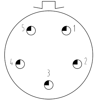
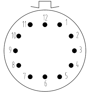
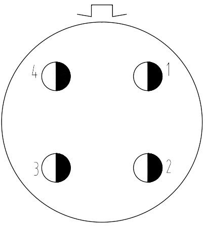
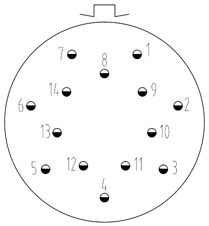
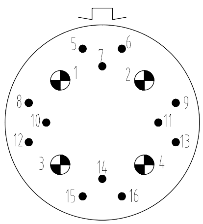
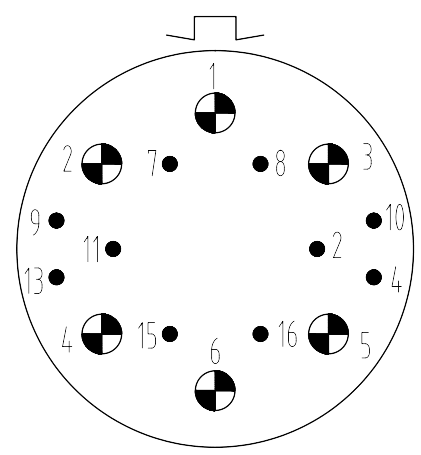
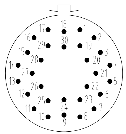
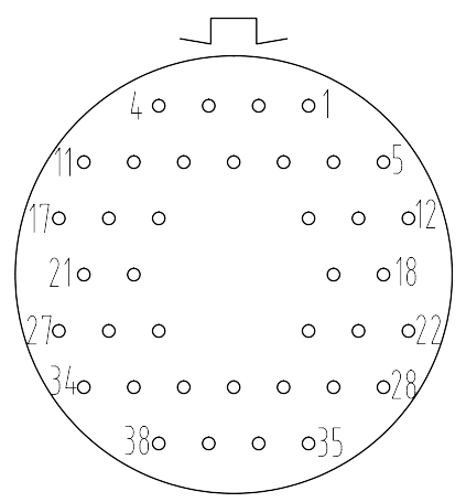
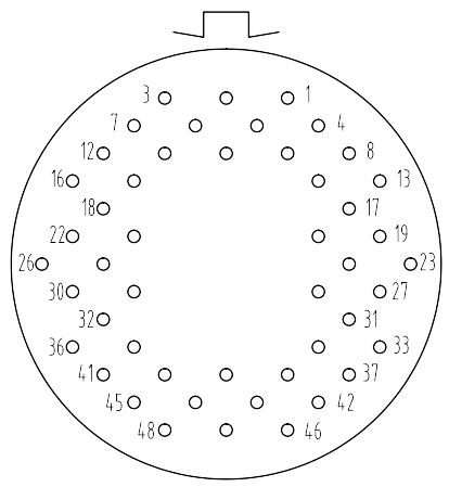
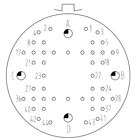
Contact arrangement
| Contact Spec | ||||||
 |
 |
 |
 |
|||
| 1 | 1.3 | 1.5 | 2.5 | 3 | 3.5 | 5 |
| 18 | 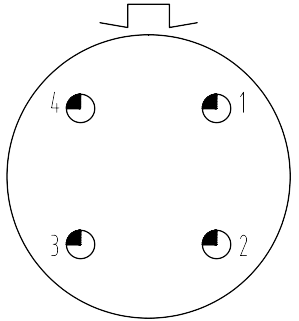 |
 |
 |
| 1804 | 1805 | 1812 | |
| 24 | 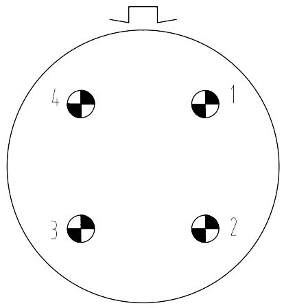 |
 |
 |
| 2404 | 2404I | 2414 | |
 |
 |
 |
|
| 2416 | 2416I | 2430 | |
 |
 |
||
| 2438 | 2448 | ||
| 30 | 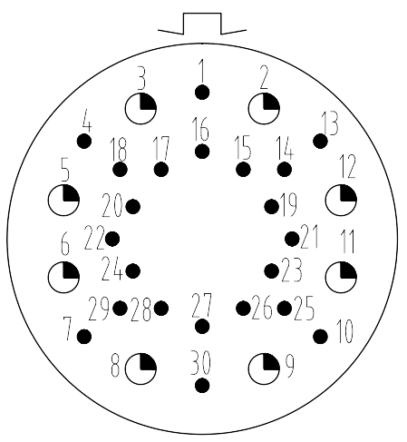 |
 |
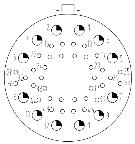 |
| 3048 | 3048I | 3030 |
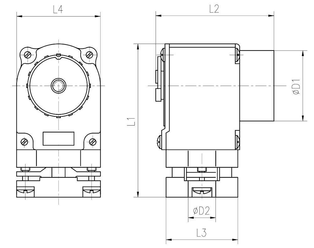
Drawings
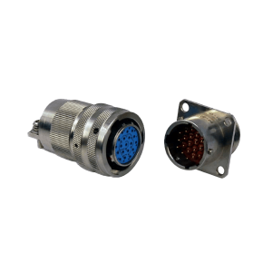
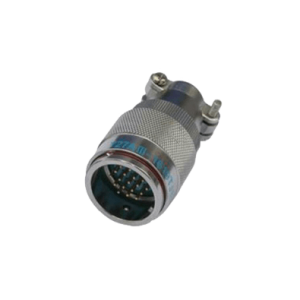
- Plug
 |
||||||||||
| Specification No. | L3 | L4 | D1 | L1 | L2 | D2 | ||||
| P | H | P | H | P | H | |||||
| 18 | 25 | 31.5 | 38 | 28 | 69.5±3 | 42±2 | 48.5±2 | 12 | 12.5 | |
| 24 | 2404
2404I 2414 2430 2438 2448 |
31.5 | 38 | 48 | 38 | 71.5±3 | 48.5±2 | 55±2 | 18 | 22 |
| 2416
2416I |
38 | 58.5 | 48 | 38 | 77.5±3 | 55±2 | 75.5±2 | 22 | 23.5 | |
| 30 | 57 | 51 | 41 | 77.5±3 | 55±2 | 26.5 | ||||
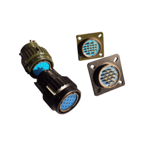
- Nut mounting socket
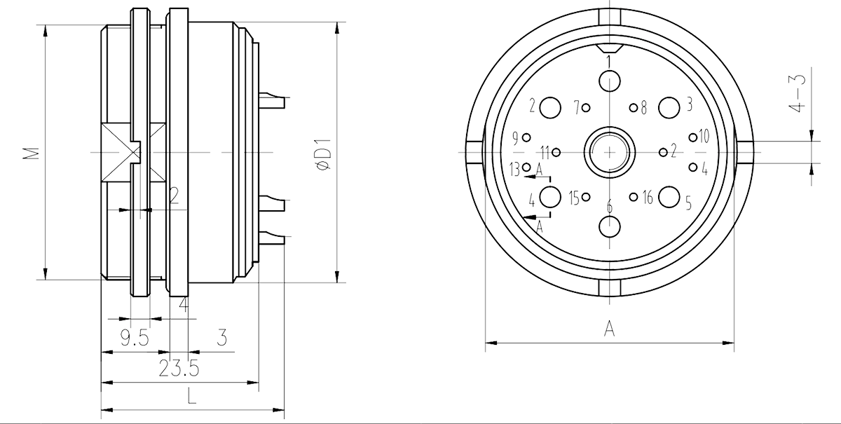 |
|||||
| Specification No. | L | D1 | M | A | |
| 18 | 1804
1805 |
28±2 | 33 | M32x1.5 | 30 |
| 1812 | 26.5±2 | ||||
| 24 | 2404
2404I 2414 |
26.5±2 | 43 | M42x1.5 | 40 |
| 2416 | 29±2 | ||||
| 2416I | 28±2 | ||||
| 2430
2438 2448 |
26.5±2 | ||||
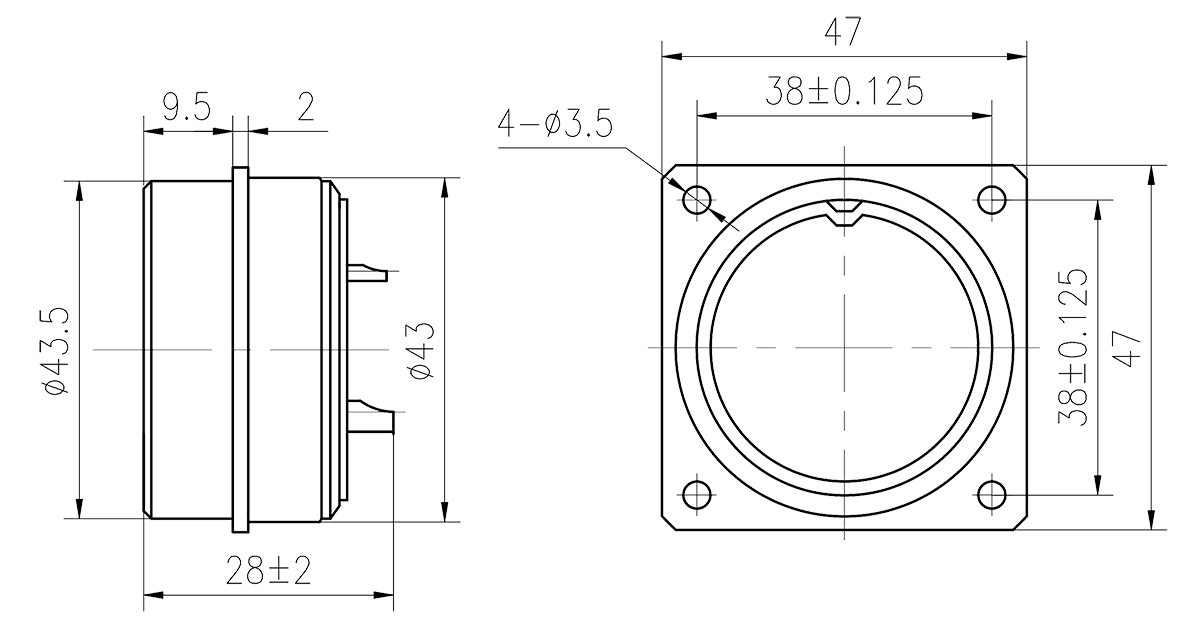
- Square Flange Receptacle
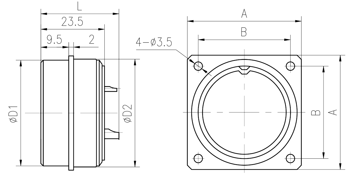 |
||||||
| Specification No. | D1 | D2 | L | A | B | |
| 18 | 1804
1805 |
32 | 33 | 28±2 | 38 | 30±0.125 |
| 1812 | 26.5±2 | |||||
| 24 | 2404
2404I 2414 |
42 | 43 | 26.5±2 | 47 | 38±0.125 |
| 2416 | 29±2 | |||||
| 2416I | 28±2 | |||||
|
2430 2438 2448 |
26.5±2 | |||||
| 30 | 45 | 46 | 29±2 | 52 | 41±0.125 | |
- Through wall Receptacle
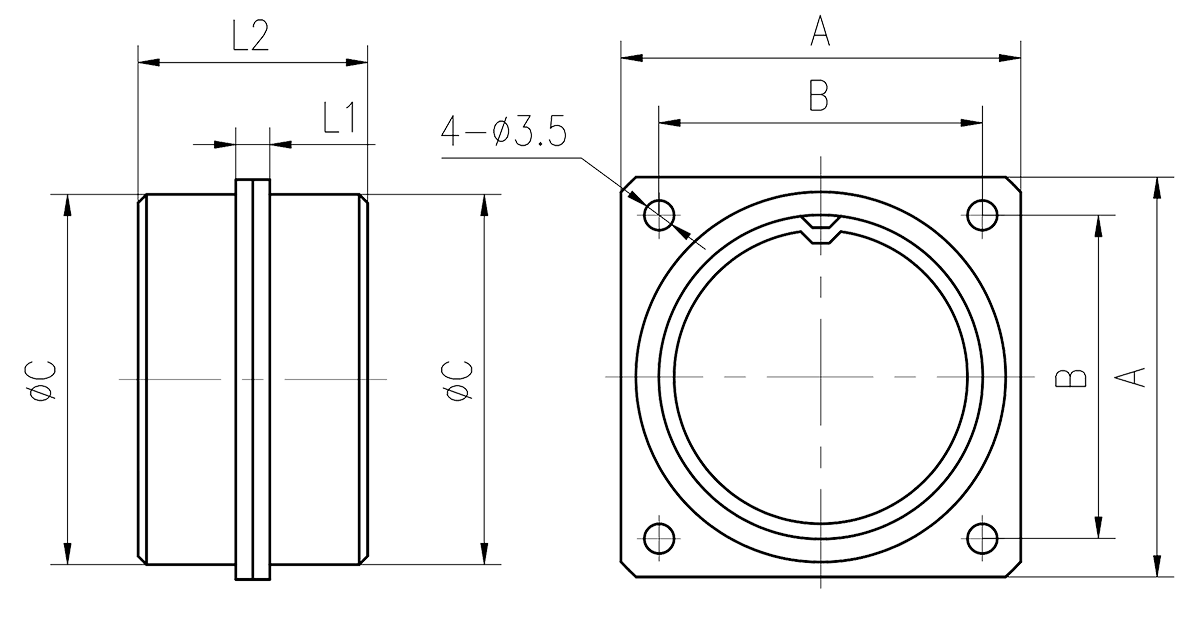 |
||||||
| Specification No. | A | B | C | L1 | L2 | |
| 18 | 38 | 30±0.125 | 32 | 3 | 35±2 | |
| 24 | 2416
2416I 2438 |
47 | 38±0.125 | 42 | 3 | 35±2 |
| 30 | 3048I | 52 | 41 ±0.125 | 45 | 3 | 35±2 |
- Y16E-2416I Square Flange Glass Sealing Receptacle