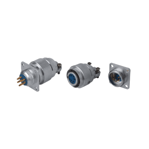
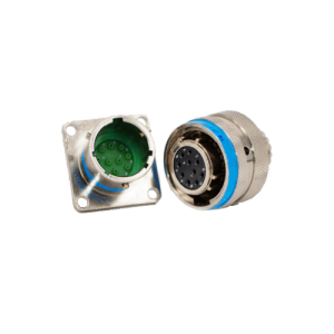
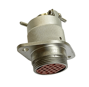
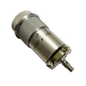
Y27 series Electrical Connector
Environmental Specifications
|
Operating temperature |
-55 ~ +125°C | Sinusoidal Vibration | 10 Hz ~ 2000 Hz, 196 m/s2 |
|
Operating Pressure |
1.33 Pa ~ 101.3 kPa | Random Vibration | Power spectral density 0.4g2/Hz, Acceleration rms value 23.1g |
|
Relative humidity |
95% at 40°C | Shock | 980 m/s2 |
|
Immersion |
2m depth (only Y27F, G, H series) | Constant acceleration |
980 m/s2 |
|
Electromagnetic interference shielding |
45dB minimum attenuation @ interference frequency is 100MHz~1GHz |
||
| Salt spray resistance |
Y27, Y27A, B, C series: 48 hours, |
||
- Electrical continuity between enclosures:
- Aluminum case: 0.01Ω
- One of the plug or receptacle housings is stainless steel or iron alloy: 0.05Ω
Receptacle hermeticity
- Rubber seal: Maximum leakage rate is 1 pa.cm3/s
- Sintered seal: Maximum leakage rate is 1×10⁻⁴cm3/s
- Mechanical life: 500 times
Electrical performance (contact resistance mΩ)
|
Mating diameter (mm) |
0.8 | 1.0 | 1.5 | 2.5 | 3.5 | 5.0 | 7.0 | 9.0 | 10.0 | 12.0 | ||||
|
Material |
Copper | Iron | Copper | Iron | Copper | Iron | Copper | Iron | Copper | Copper | Copper | Copper | Copper | Copper |
|
Before the life test |
12 |
25 | 10 | 12 | 7 | 10 | 1.5 | 5 | 1 | 0.7 | 0.5 | 0.4 | 0.4 |
0.3 |
|
After life test |
15 | 32 | 12 | 20 | 10 | 15 | 3 | 10 | 1.5 | 1 | 0.8 | 0.7 | 0.6 |
0.5 |
Electrical performance (contact current rating A)
|
Contact diameter (mm) |
0.8 | 1.0 | 1.5 | 2.5 | 3.5 | 5.0 | 7.0 | 9.0 | 10.0 | 12.0 | |
|
Contact current rating |
Y27 |
3 | — | — | — | — | — | — | — | — | |
|
Y27A |
— | 5 | — | — | — | — | — | — | — | ||
|
Y27B |
— | 5 | 10 | 25 | 50 | 75 | 100 | 150 | 200 | — | |
| Y27C | — | 5 | 10 | 25 | 50 | 75 | 100 | 150 | 200 |
— |
|
| Y27F | — | 7.5 | — | — | — | — | — | — |
— |
||
| Y27G | — | 7.5 | 13 | 25 | 50 | 75 | 100 | 150 | 200 |
250 |
|
| Y27H | 3 | 5 | — | — | — | — | — | — |
— |
||
Electrical performance (withstand voltage V)
|
series |
Test voltage (50Hz AC RMS) | ||||||
|
Y27 |
Y27A | Y27B | Y27C | Y27F | Y27G | Y27H | |
| Normal condition | 750 | 1300 | 1500 | 2500 | 2300 | 2300 |
1300 |
| Low air pressure≤ 1.33pa | 100 | 200 | 200 | 300 | 200 | 200 |
200 |
Electrical performance (Insulation resistance MΩ)
|
Series |
Y27 | Y27A | Y27B | Y27C | Y27F | Y27G | Y27H | |
|
Normal Condition |
1000 | 4000 | 5000 | 5000 | 5000 | 5000 | 4000 | |
|
High Humidity |
Ordinary | 500 | 1000 | 1000 | 1000 | 1000 | 1000 | 1000 |
|
Sintering |
200 | 200 | 200 | 200 | 200 | 200 |
— |
|
| Moist | 50 | 100 | 100 | 100 | 100 | 100 |
100 |
|
| Rain | 20 | 20 | 20 | 20 | — | — |
— |
|
| Immersion | — | — | — | — | 20 | 20 |
20 |
|
Plug Ordering format
Example: Y27AII-0804TJLFII-B
| Y27 | A | II | – | 08 | 04 | T | J | L | F | II | – | B | |
| Main code | Y27 | ||||||||||||
| Series number | A | ||||||||||||
| Primary and secondary key angle recognition | II | ||||||||||||
| Shell number | 08 | ||||||||||||
| Number of contacts | 04 | ||||||||||||
Shell type;
|
T | ||||||||||||
Contact type:
|
J | ||||||||||||
Type:
|
L | ||||||||||||
| Separation form | F | ||||||||||||
| Tail attachment form | II | ||||||||||||
Shell material type:
|
B |
Note:
(1) The identification numbers of the main keyway and the auxiliary keyway are: I (not shown), II, III.
(2) The number of shells and the number of contacts in each sub-series are shown in the spectrum description.
(3) Contact type:
Y27 series: J1 (K1) means that the contact wire is flat and arranged in two directions: back to back.
Y27A series:
- J (K) means that the contact wire is flat and aligned in two directions.
- J1 (K1) means that the contact wire is flat and arranged in two directions: back to back.
- J3 (K3) means that the contact piece is crimped and detachable.
- J4 (K4) means that the contact wires are flat and aligned in one direction.
Y27B series: J (K) means that the contact wire is flat and aligned in one direction.
Y27C series:
- J (K) means that the contact wires are flat and aligned in one direction.
- J1 (K1) means that the contact wire is flat and aligned in two directions.
Y27F series: J (K) means that the contact wires are flat and aligned in one direction.
Y27G series:
- J (K) means that the contact wires are flat and aligned in one direction.
- J1 (K1) means that the contact wire is flat and aligned in two directions.
(4) Separation form: A (not marked) – push / pull type,
F – pull line separate type.
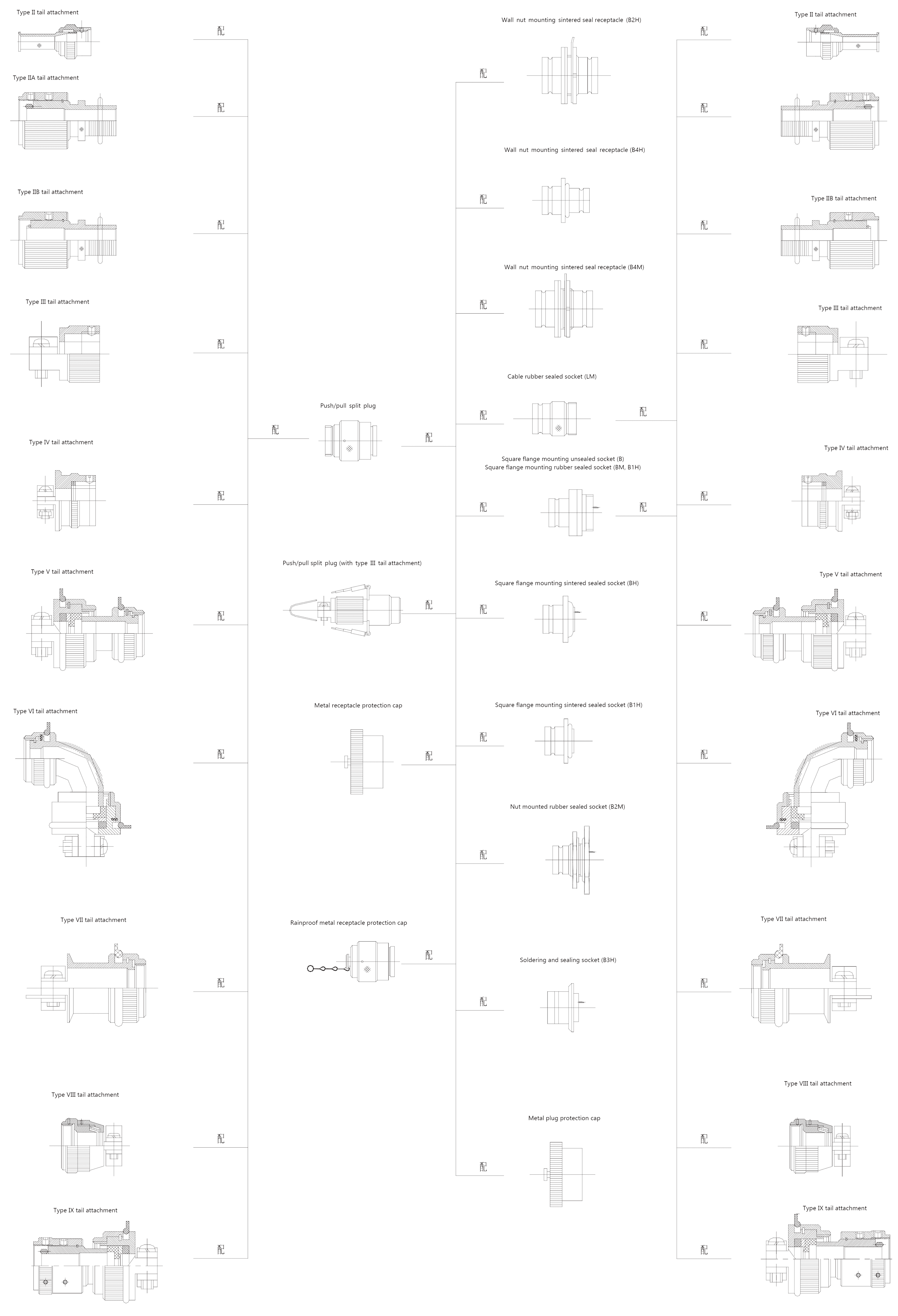
(5) Back-shell form:
- Omit – no Back-shell,
- II – with type II,
- III – with type III,
- IV—with type IV,
- V—with V type,
- VI—with type VI,
- VII—with type VII;
The Y27A, B, and C series can only be equipped with II, II A, III, and VI tail attachments. The specific supporting situation is shown in the attached article.
(6) Housing material category: B, C is suitable for marine environment.
Example:
Y27A Series No. 08 housing with 4-pin plug, primary and secondary key angle II, with Type III tail attachment, model Y27AII- 0804TJLIII
Receptacle Ordering format
Example: Y27AII-0804ZJLFII-B
| Y27 | A | II | – | 08 | 04 | Z | J | L | F | II | – | B | |
| Main code | Y27 | ||||||||||||
| Series number | A | ||||||||||||
| Primary and secondary key angle recognition | II | ||||||||||||
| Shell number | 08 | ||||||||||||
| Number of contacts | 04 | ||||||||||||
Shell type;
|
Z | ||||||||||||
Contact type:
|
J | ||||||||||||
| Mounting type | L | ||||||||||||
| Seal form | F | ||||||||||||
| Back-shell form | II | ||||||||||||
Shell material type:
|
B |
Note:
(1) The identification numbers of the primary and secondary keyway are: I (not shown), II, III.
(2) The number of shells and the number of contacts in each sub-series are shown in the spectrum description.
(3) Contact type:
Y27 series: J1 (K1) means that the contact wire is flat and arranged in two directions: back to back.
Y27A series:
- J (K) means that the contact wire is flat and aligned in two directions.
- J1 (K1) means that the contact wire is flat and arranged in two directions: back to back.
- J3 (K3) means that the contact piece is crimped and detachable.
- J4 (K4) means that the contact wires are flat and aligned in one direction.
Y27B series: J (K) means that the contact wire is flat and aligned in one direction.
Y27C series:
- J (K) means that the contact wires are flat and aligned in one direction.
- J1 (K1) means that the contact wire is flat and aligned in two directions.
Y27F series: J (K) means that the contact wires are flat and aligned in one direction.
Y27G series:
- J (K) means that the contact wires are flat and aligned in one direction.
- J1 (K1) means that the contact wire is flat and aligned in two directions.
(4) Installation method:
- L- Cable type,
- B-Square flange mounting
- B1- Square flange mounting,
- B2- Nut mounting,
- B3-Solder mounting;
- B4-Wall mounting (B4 type contact type J means that both ends of the receptacle are pin contacts, if contact type does not indicate, one end is a pin contact, and one end is a socket contact)
(5) Sealing form:
- P (not marked) – Unsealed,
- M-rubber seal,
- H-glass sintered seal.
The combination of the mounting mode and the sealing form of the receptacle is shown in the combination of the use.
(6) Tail attachment form: Omitted-no attachment,
- II-with type II,
- III-with type III,
- IV-with type IV,
- V—with V type,
- VI—with VI type,
- VII—with type VII;
Y27A, B, and C series can only be equipped with II, II A, III, and VI tail attachments. The specific supporting situation is shown in the attached article.
(7) Shell material category: B, C is suitable for marine environment.
Example:
Y27B series, Shell No. 12, with 3 sockets, B-type square flange mounting, primary and secondary key angle I, rubber seal, no tail Accessories, model number: Y27B-1203ZKBM
Tail attachment Ordering format
Example: Y27 10VB
| Y27 | 10 | V | B | |
| Main code | Y27 | |||
| Shell number | 10 | |||
Type:
|
V | |||
Difference No.:
|
B |
Example: It is matched with the Y27B series, Shell No. 12 plug, and the cable is packaged in the heat shrinkable sleeve type Y27-12 II.
Example: JS27F10TBLM
| JS | 27F | 10 | T | B | L | M | ||
| metal protective cap | JS | |||||||
| Applicable product series code:
27A Applicable to Y27A, B, C; 27F Applicable to Y27F, G, H; |
27F | |||||||
| Shell number:
08,10,12,14,16,18, 20, 22, 24, 26, 28, 30, 32; |
10 | |||||||
| Shell type:
T- plug, Z- receptacle; |
T | |||||||
| Shell material category:
N-aluminum alloy nickel plating, H-aluminum alloy red oxidation, B-stainless steel, C-copper alloy; |
B | |||||||
| chain type:
(not marked) – user own chain, L- with metal chain; |
L | |||||||
| Function (only for receptacle protection caps):
not marked – with Protection, |
– | |||||||
| M- rain proof protection cap; | M |
Example:
- Matched with Y27G Series plug with Shell No. 20, red oxidized surface, without metal chain, model number JS27F-20TH
Ordering guide:
- Under normal circumstances, it is preferred to use the “I” type of the key position to identify the number “I” type. When two or more products of the same type are installed on the same panel, the product with the “A” type of the key position identification number is selected.
Y27 series electrical connector plug, receptacle, tail attachment, metal protective cap combination
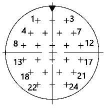
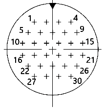
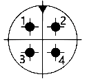
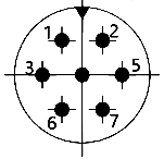
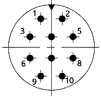
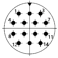
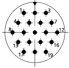
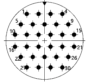
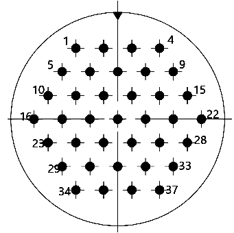
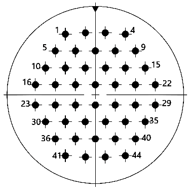
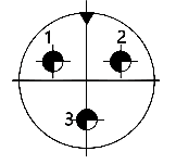
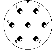
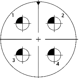
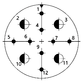
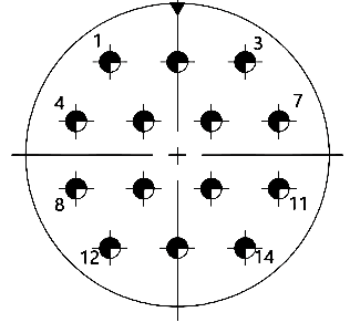
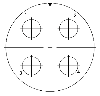
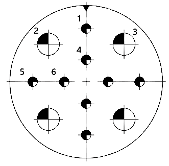
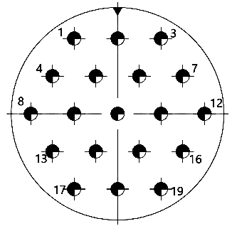
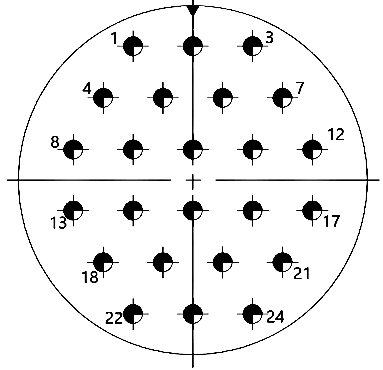
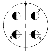
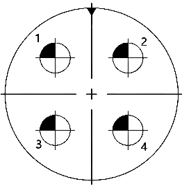
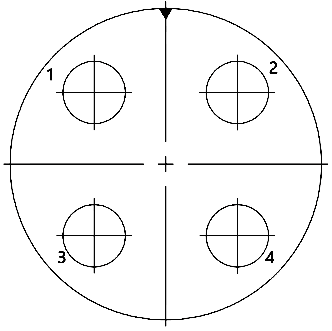
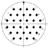
Arrangement description
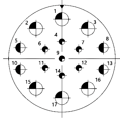
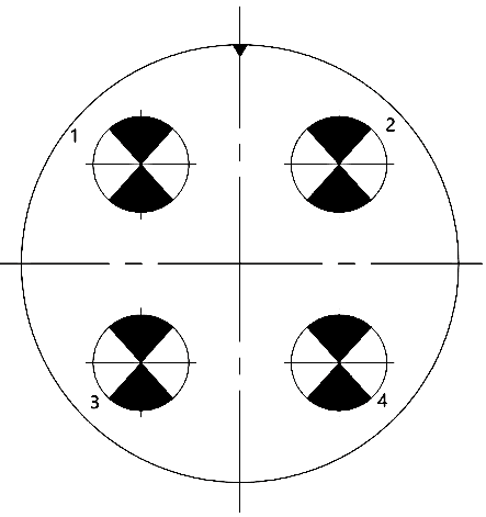
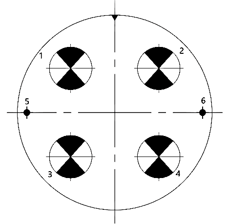
- ▼ in the spectrum indicates the position of the primary key (slot)
- The contact position number in the type spectrum refers to the hole number of the socket on the mating interface. Note: The pull-off plug and the mark code are finally W.
- The order of the hole number of the plug is opposite to that of the type spectrum.
- The four digits above the spectrum, the first two digits are the shell number, and the last two digits are the number of contacts.
- Contact specifications and indications are shown in the table below.
| Contact fitting diameter (mm) | 0.8 | 1.0 | 1.5 | 2.5 | 3.5 | 5.0 | 7.0 | 9.0 | 10.0 | 12.0 | |
| Contact current rating (A) | Y27、Y27A、B、C、H | 3 | 5 | 10 | 25 | 50 | 75 | 100 | 150 | 200 | — |
| Y27F、G | — | 7.5 | 13 | 25 | 50 | 75 | 100 | 150 | 200 | 250 | |
| Representation | ╋ | ● | |||||||||
Y27 series contact arrangement
- Y27 contact arrangement
 |
 |
 |
 |
 |
| 1424 | 1430 | 2255 | 2261 | 2485 |
- Y27A contact arrangement
 |
 |
 |
 |
 |
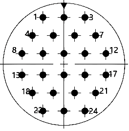 |
| 0804 | 1007 | 1410 | 1414 | 1619 | 2024 |
 |
 |
 |
 |
 |
|
| 2030 | 2237 | 2444 | 2455 | 2661 |
- Y27B contact arrangement
 |
 |
 |
 |
 |
| 1203 | 1607 | 2001 | 2004 | 2012 |
 |
 |
 |
 |
 |
| 2214 | 2404 | 2412 | 2419 | 2624 |
- Y27C contact arrangement
 |
 |
 |
 |
 |
 |
| 1604 | 2004 | 2604 | 2617 | 3004 | 3006 |
- Y27F contact arrangement
 |
 |
 |
 |
 |
| 1004 | 1610 | 1814 | 2019 | 2224 |
 |
 |
 |
 |
|
| 2430 | 2637 | 2844 | 2855 |
- Y27G contact arrangement
 |
 |
 |
 |
| 1003 | 1203 | 1204 | 1405 |
 |
 |
 |
 |
| 1407 | 1604 | 1810 | 2004 |
 |
 |
 |
 |
| 2210 | 2014 | 2424 | 2612 |
 |
 |
 |
 |
| 2837 | 3203 | 3204 | 3255 |
- Y27H contact arrangement
 |
 |
 |
| 2885 | 28121 | 2692 |